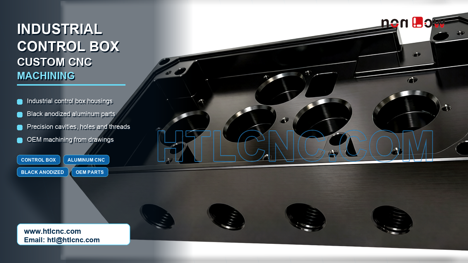
A machining-focused review of black anodized industrial control housings with deep cavities, large bores, threaded interfaces and drawing-based OEM production support.
Industrial control housings often combine a rigid exterior, deep internal cavities and multiple interfaces for mounting, connectors, controls or adjacent assemblies. The black component shown here includes several large circular bores, smaller threaded features, deep pockets, stepped faces and a long structural wall. Producing these features consistently requires more than machining the visible outside profile.
HTL CNC manufactures custom industrial control housings, equipment boxes and precision structural components from customer drawings, STEP files and approved samples. We support engineering prototypes, low-volume validation and repeat OEM production. Material grade, dimensional tolerances, anodizing specification and final application must always follow the customer's approved technical documents.
Deep-Cavity Milling and Tool Access
Deep cavities can create challenges in tool reach, chip evacuation, vibration and surface consistency. Long tools may reduce rigidity, while narrow internal spaces can limit the available cutter diameter and approach direction. Process planning should consider roughing allowance, tool length, corner radii, step-down strategy and the sequence used to finish walls and floors.
Where several faces contain functional features, 4-axis or 5-axis machining may reduce reclamping and improve access. However, the correct route depends on the actual drawing, datum structure, tolerance relationships and production quantity. A practical manufacturing plan balances machine capability with stable fixturing and inspection access.
Large Bores, Threads and Assembly Interfaces
The visible housing contains large machined bores and repeated threaded openings. These features may locate shafts, connectors, covers, fittings or other assemblies, so their diameter, position, depth and relationship to mating faces can be more important than the general exterior surface.
Thread quality should be verified after machining and again after surface treatment when coating could affect fit. Drawings should identify critical bores, thread class, masked areas, grounding points, sealing faces and any surfaces that must remain free of anodizing.
Managing Wall Stability and Surface Quality
Removing a large volume of material can change part stiffness as machining progresses. Fixtures must support the component without distorting long walls or cosmetic faces. A controlled roughing and finishing sequence can help manage cutting force, residual stress and vibration around cavities and thin sections.
Black finishes make scratches, dents and inconsistent texture easier to see. Cosmetic zones, acceptable color range, gloss level and handling requirements should therefore be agreed before production. Edge breaks and deburring also require attention around intersecting holes, deep pockets and openings that may contact wiring or assembly personnel.
Black Anodizing and Dimensional Allowance
Black anodizing is commonly specified for aluminum equipment housings when surface protection and a clean technical appearance are required. Final color and texture can vary with alloy, pretreatment, blasting or brushing, coating process and part geometry. The material and finish shown in a photograph should never replace the specification in the customer's drawing.
Critical fits, threads, sealing surfaces and electrical contact regions may need masking or dimensional allowance. Confirming these requirements during quotation helps prevent a dimensionally correct machined part from developing assembly problems after finishing.
Inspection from Prototype to Repeat Production
Inspection planning can include cavity depth, bore diameter, hole position, thread verification, wall thickness, mating-face relationships and flatness where specified. Calipers, micrometers, gauges, height measurement and CMM inspection may be used according to the approved quality plan.
Prototype production allows engineering teams to check fit, access, assembly sequence and finish before repeat quantities are released. After approval, controlled programs, repeatable fixtures, revision management and defined inspection points support stable OEM manufacturing.
For an engineering review and quotation, send your 2D drawing, STEP file, specified material, quantity, critical tolerances, inspection requirements and surface-finish notes.
Website: www.htlcnc.com Email: htl@htlcnc.com WhatsApp: +1 936 358 5257 Mobile: +86 186 8244 4204
Have a part ready for engineering review?
Send your drawing, STEP file, material and quantity directly to HTL CNC for a manufacturing quotation.