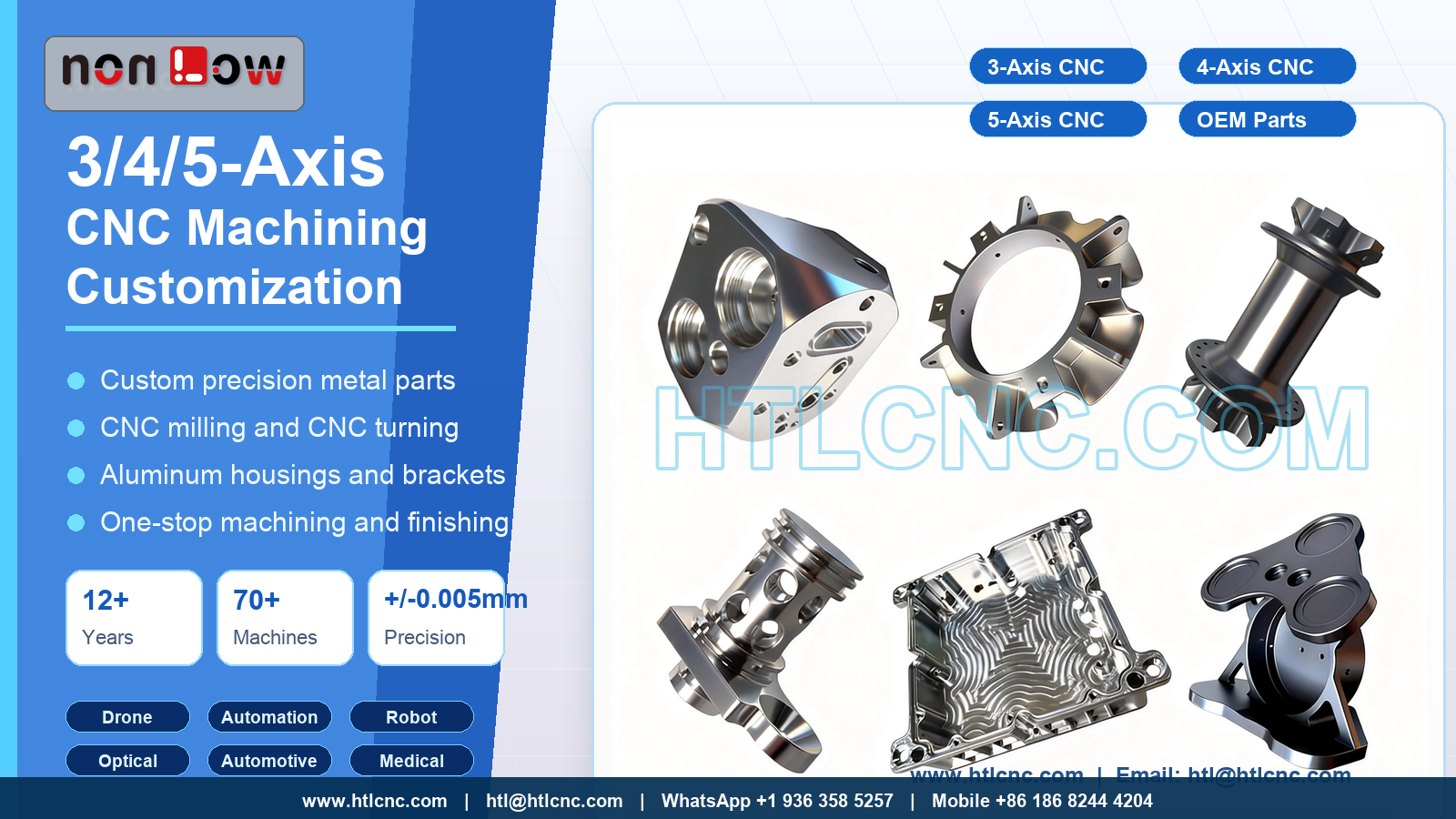
A practical guide to selecting 3-axis, 4-axis or 5-axis CNC machining for custom metal parts based on feature access, datum relationships, setup count and inspection needs.
Custom CNC parts can range from straightforward plates and housings to components with angled faces, deep cavities, radial holes, compound surfaces and features distributed around several sides. Selecting 3-axis, 4-axis or 5-axis machining should therefore begin with the drawing and 3D model rather than with the appearance of the finished part alone.
HTL CNC manufactures drawing-based custom parts for engineering prototypes, low-volume production and repeat OEM orders. We review feature access, datum relationships, setup requirements, material, quantity, inspection needs and surface-finish notes before recommending a machining route. The correct process is the one that can manufacture and verify the approved design efficiently and consistently.
When 3-Axis CNC Machining Is Suitable
Three-axis machining controls tool movement along the X, Y and Z directions. It is commonly suitable for plates, brackets, covers, panels, pockets, hole patterns and housings whose critical features can be reached from a limited number of orientations. A component may still require more than one setup, but each operation uses a fixed workpiece orientation.
For suitable geometry, 3-axis machining can provide an efficient route with widely available tools and straightforward fixturing. Process planning should still consider pocket depth, internal corner radius, tool reach, chip evacuation and the relationship between features produced in separate setups. Critical positional requirements should be identified clearly in the drawing.
Where 4-Axis Machining Adds Value
Four-axis machining adds controlled rotation around one axis. This can support components with repeated features around a cylindrical body, radial holes, multiple side faces or indexed machining positions. The rotary axis may reduce manual reclamping and help maintain relationships between features placed around the part.
A 4-axis route can be useful for shafts, rings, circular frames, housings and structural components that require access at several indexed angles. However, fixture clearance, rotary travel, workholding rigidity and tool access must be reviewed against the complete model. Some features may still require an additional operation or a different machine configuration.
Why 5-Axis CNC Machining Is Used
Five-axis machining provides controlled movement across three linear axes and two rotary axes. It can improve access to angled faces, compound surfaces, deep cavities and features located on several sides of a complex component. In suitable cases, fewer setups can help preserve datum relationships and reduce repeated handling.
Five-axis capability does not automatically make every part faster or more accurate. Tool length, collision clearance, workholding, machine kinematics, surface requirements, programming strategy and inspection access all influence the result. The route should be selected from the actual geometry and tolerance structure, not simply from a preference for more axes.
Combining CNC Milling and CNC Turning
Some custom parts include both rotational geometry and milled features. These components may use CNC turning, turn-mill machining, separate turning and milling operations or a multi-axis milling route. The choice depends on part size, concentric relationships, feature orientation, production quantity and available inspection methods.
Turned diameters, grooves and faces may be produced efficiently on a lathe, while pockets, slots, cross holes and mounting features require milling access. Planning the datum transfer between operations is important when the drawing defines relationships between rotational and prismatic features.
Setup Count and Datum Relationships
Every setup introduces decisions about locating, clamping and verifying the workpiece. Reducing setup count can help maintain relationships between features, but only when the selected fixture and machine provide stable access. A well-planned two-setup route may be more reliable than forcing every feature into one complex operation.
The drawing should define functional datums and critical tolerances so manufacturing and inspection use the same reference structure. Position, profile, perpendicularity, concentricity, flatness and runout requirements should be reviewed together with the assembly function of the part.
Material, Tooling and Surface Finish
Machining strategy also depends on the specified material and stock condition. Aluminum alloys, steels, stainless steels, copper alloys, titanium alloys and engineering plastics can require different tools, cutting parameters, coolant approaches and support methods. Exact material grades must be confirmed in the RFQ package.
Surface treatment should be planned before production. Anodizing, plating, passivation, blasting, brushing, polishing, painting or another finish may affect dimensions, masking requirements, threaded features and cosmetic zones. The approved drawing should identify areas that require protection or a defined appearance.
Inspection Planning for Multi-Axis Parts
Complex parts need an inspection plan that follows their functional requirements. Verification may include external dimensions, pocket depths, hole positions, bore diameters, thread checks, angular relationships, profiles and datum-based feature locations. Calipers, micrometers, height measurement, gauges, optical equipment and CMM inspection may be used according to the agreed plan.
Inspection access should be considered during process development. A feature that is easy to machine may still require a specific fixture or probing strategy for reliable measurement. Prototype production can help confirm the machining route, assembly fit and inspection method before repeat quantities are released.
RFQ Information for Custom CNC Parts
For an accurate engineering review, provide the 3D model and 2D drawing together. Include the specified material, quantity, critical tolerances, threads, surface finish, inspection requirements and any assembly relationships that affect function. STEP files are useful for geometry, while the drawing should remain the authority for tolerances and notes.
HTL CNC supports 3-axis, 4-axis and 5-axis CNC machining, CNC turning and turn-mill manufacturing for custom parts made from approved customer documents. Send your project information for prototype, low-volume or OEM production review.
Website: www.htlcnc.com Email: htl@htlcnc.com WhatsApp: +1 936 358 5257 Mobile: +86 186 8244 4204
Have a part ready for engineering review?
Send your drawing, STEP file, material and quantity directly to HTL CNC for a manufacturing quotation.