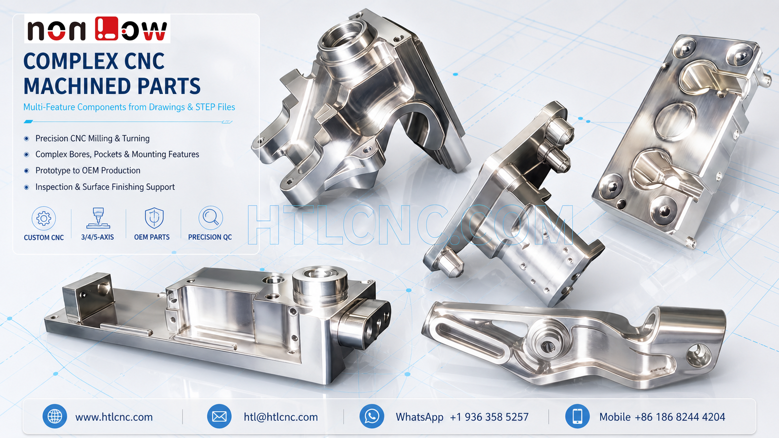
Drawing-based CNC manufacturing for complex custom parts with bores, pockets, slots, mounting faces and features distributed across multiple orientations.
Complex CNC machined parts often combine prismatic surfaces, rotational details, mounting faces, bores, pockets, slots and features positioned across several orientations. The parts shown here illustrate different geometry types rather than one standard product family. Each component requires a manufacturing route based on its released drawing, STEP model, specified material, tolerance structure, quantity and inspection requirements.
HTL CNC manufactures drawing-based custom parts for engineering prototypes, low-volume validation and repeat OEM production. We work with overseas engineering teams, contract manufacturers, equipment builders and procurement departments that need a responsive CNC machining supplier for new-product introduction and repeat purchasing. We review the actual geometry before selecting CNC milling, CNC turning, turn-mill machining, indexed machining or a multi-setup process. Appearance alone does not establish a material grade, tolerance or final application, so these requirements must come from the customer's approved documents.
B2B Project Review and Supplier Qualification
A B2B machining program normally begins with technical and commercial information rather than a catalog selection. Buyers may need a manufacturability review, quotation breakdown, sample plan, inspection approach, packaging requirements and an agreed route from first articles to repeat orders. Clear drawings and revision control help both purchasing and engineering teams compare suppliers on the same basis.
For supplier onboarding, customers can identify critical dimensions, required inspection records, approved finishing specifications, target quantities, delivery milestones and any document requirements in the RFQ. HTL CNC can review this package and align machining, quality checks and production planning with the approved purchase order and technical files. Confidential drawings and project information should be handled as controlled customer documents throughout quotation and production.
Mixed Prismatic and Rotational Features
A custom component may include flat datum faces and machined pockets together with cylindrical bosses, bores, counterbores, threads or turned diameters. Where rotational features are central to the design, CNC turning or turn-mill machining may provide an efficient starting route. Where the main form is irregular, CNC milling may establish the outside profile, mounting surfaces and internal features.
The best sequence depends on which features control assembly. If a bore must remain related to a milled face or hole pattern, datum transfer between operations becomes important. Process planning should identify which setup establishes the primary references and how later operations reproduce those relationships without unnecessary reclamping error.
Bores, Pockets and Mounting Interfaces
The visible parts contain large openings, recessed areas, local bosses and multiple mounting features. Bores may require drilling, interpolation, boring, reaming or another drawing-approved method according to diameter, depth and tolerance. Pocket machining requires review of tool access, internal corner radius, cutter reach and chip evacuation.
Mounting interfaces should be treated as functional geometry rather than decoration. Hole position, face orientation, boss height and thread condition can influence assembly even when the surrounding surface is not dimensionally critical. The drawing should identify key datums and tolerances so machining and inspection focus on the correct relationships.
Slots, Thin Sections and Edge Features
Long slots, cutouts, narrow bridges and local thin sections can change component stiffness as material is removed. Roughing and finishing sequences should leave adequate support around sensitive regions. Controlled tool engagement and suitable workholding can help reduce vibration, burr formation and movement during final passes.
Deburring must remove sharp material without enlarging slots, rounding functional edges or changing hole conditions. Where a customer requires a defined edge break, chamfer or radius, that requirement should be stated on the drawing instead of being inferred from a visual reference.
Choosing 3-Axis, 4-Axis or 5-Axis Access
Some multi-feature parts can be produced with 3-axis machining and several controlled setups. Others may benefit from 4-axis indexing when features repeat around a body, or 5-axis machining when angled surfaces and multiple orientations require improved access. The number of visible faces does not automatically determine the machine choice.
Fixture clearance, tool reach, collision risk, datum relationships, production quantity and inspection access should be evaluated together. Reducing setup count can support consistency, but only when the selected fixture provides stable support and the machine can reach the required geometry without compromising tool rigidity.
Workholding and Process Stability
Irregular parts may offer limited clamping area after early operations remove stock. Fixtures, soft jaws or custom supports should locate the workpiece repeatably while keeping clamps away from cutting paths and important cosmetic surfaces. Excessive force can distort a thin or uneven component during machining and allow it to move after release.
A practical process may establish reference faces first, remove bulk material in balanced stages and reserve controlled finishing passes for critical features. The exact sequence depends on material behavior, stock condition, part geometry and drawing requirements. Prototype production can help confirm access, workholding and inspection before repeat quantities are released.
Inspection of Multi-Feature Components
Inspection may include outside dimensions, profiles, bore diameters, pocket depths, slot widths, hole positions, thread checks, mounting-face relationships and datum-based geometry. Calipers, micrometers, height measurement, pin or thread gauges, optical equipment and CMM inspection may be used according to the agreed quality plan.
The inspection method should match the feature and tolerance. Critical dimensions and geometric requirements need to be identified in the drawing so measurement resources are applied appropriately. Revision control is also essential when prototypes develop into OEM production, because programs, fixtures and inspection records must follow the approved design version. Where requested, the RFQ should state the expected first-article, dimensional or batch documentation so scope and delivery can be agreed before production.
Surface Finish and Post-Processing
Parts may be supplied as machined or prepared for a customer-specified treatment compatible with the approved material. Anodizing, plating, passivation, blasting, brushing, polishing, painting or another finish should be selected only from the drawing and application requirements. Coating allowance, masking, thread protection and cosmetic acceptance criteria should be reviewed before quotation.
Surface preparation should preserve functional geometry. Recessed pockets, internal bores and threaded holes may need special cleaning or protection, while visible faces may require controlled handling and export packaging to reduce scratches during storage and transport.
From Prototype to Repeat B2B Orders
Prototype quantities allow engineering and sourcing teams to review assembly fit, feature access, edge quality, inspection methods and finish requirements. After sample approval, repeatable programs, controlled fixtures, documented inspection points, revision management and purchasing forecasts support stable low-volume and OEM manufacturing.
For an efficient B2B quotation, send the 2D drawing and STEP file together with the specified material, target quantity or annual demand, critical tolerances, threads, inspection requirements, surface-finish notes, delivery destination and expected schedule. This information helps the supplier prepare a realistic process and commercial review instead of a generic price estimate.
Website: www.htlcnc.com Email: htl@htlcnc.com WhatsApp: +1 936 358 5257 Mobile: +86 186 8244 4204
Have a part ready for engineering review?
Send your drawing, STEP file, material and quantity directly to HTL CNC for a manufacturing quotation.