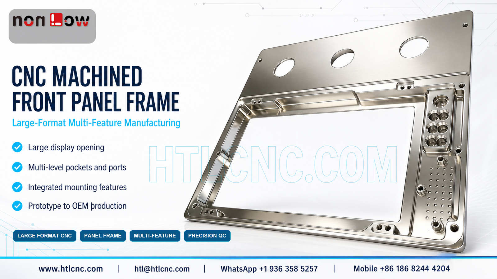
Drawing-based CNC manufacturing for large equipment front panel frames with display openings, recessed pockets, mounting features and multiple interface ports.
Large equipment front panel frames often combine a broad display opening with recessed channels, circular interface ports, mounting holes, local pockets and small perforation patterns. The component shown here integrates these features into one structural panel. Its large overall footprint and uneven material distribution make machining sequence, fixturing and inspection planning especially important.
HTL CNC manufactures custom front panel frames, equipment faceplates and large multi-feature machined components from customer drawings, STEP files and approved samples. We support engineering prototypes, low-volume validation and repeat OEM production. Material, dimensions, tolerances, surface treatment and end use must follow the customer's approved technical documents.
Large-Format CNC Milling Strategy
A large front panel can lose stiffness as the central display opening and surrounding recesses are machined. The process plan should consider stock support, clamping position, roughing order and finishing allowance before material removal begins. Balanced machining can help reduce uneven stress release, while controlled final passes can protect the broad perimeter and drawing-defined mating surfaces.
Machine travel, fixture clearance and tool reach must be checked against the complete model. Large-format capability alone does not guarantee accuracy. The selected setup must also maintain stable datum relationships and allow chips to leave deep or narrow areas without damaging finished surfaces.
Display Opening, Pockets and Perimeter Features
The large central opening is surrounded by a stepped frame with local reliefs and mounting details. Its size, corner geometry and relationship to the external perimeter may affect assembly with a display, cover or adjacent module. Drawing-defined edge conditions, corner radii and profile tolerances should be reviewed before programming.
Recessed channels and multi-level pockets can require different tool diameters and finishing paths. Larger cutters may remove bulk material efficiently, while smaller tools finish local corners and narrow transitions. Rest machining should be applied only where required by the approved geometry. The machining route must preserve the visible bosses, tabs and perimeter walls rather than simplifying them.
Multiple Ports and Integrated Mounting Details
The panel includes several large circular openings, grouped cylindrical pockets, smaller drilled holes and mounting locations. These features may serve different interfaces, but their exact function should not be assumed without the assembly drawing. Hole diameter, position, depth, thread specification and relationship to the selected datums must follow the released design.
Grouped features can require careful tool selection and chip evacuation, particularly where pockets are close together or positioned near a thin wall. Where threads or precision bores are specified, suitable gauging and measurement should be included in the agreed inspection plan. Intersections and edges should be deburred without changing functional geometry.
Fixturing, Flatness and Distortion Control
A broad panel may be sensitive to clamping force. Excessive pressure can temporarily flatten or twist a part during machining, allowing it to move after release. Fixtures should support the component securely while avoiding force that masks its free-state condition. Locating points, clamps and supports should remain clear of cutting paths and critical cosmetic zones.
The manufacturing sequence may alternate roughing, stress equalization and finishing operations depending on the material, stock condition and drawing requirements. If flatness, profile or positional relationships are critical, those requirements should be identified during quotation so machining and inspection resources can be planned correctly.
Surface Finish and Edge Quality
The visible metal surfaces can be supplied as machined or prepared for a customer-specified finish. Anodizing, plating, passivation, blasting, brushing, polishing, painting or another treatment may be appropriate only when compatible with the specified material and drawing. Coating thickness, masking zones, thread protection and cosmetic acceptance criteria should be confirmed before production.
Large openings, circular ports and fine perforation patterns create many edges that require controlled deburring. The goal is to remove burrs while preserving edge breaks, hole diameters and assembly interfaces. Any visible tool marks or directional finish requirements should be defined by the customer's approved standard.
Inspection for Prototype and OEM Production
Verification may include external profile, display-opening geometry, pocket depths, hole positions, bore diameters, thread checks, mounting-feature locations and relationships between the panel face and selected datums. Calipers, micrometers, height measurement, pin or thread gauges, optical systems and CMM inspection may be used according to feature size and the agreed quality plan.
Prototype production helps engineering teams evaluate assembly fit, panel stiffness, interface alignment, edge quality and surface-treatment requirements before repeat quantities are released. After approval, controlled programs, repeatable fixtures, revision management and documented inspection points support stable OEM manufacturing.
For engineering review and an RFQ, send your 2D drawing, STEP file, specified material, quantity, critical tolerances, inspection requirements and surface-finish notes.
Website: www.htlcnc.com Email: htl@htlcnc.com WhatsApp: +1 936 358 5257 Mobile: +86 186 8244 4204
Have a part ready for engineering review?
Send your drawing, STEP file, material and quantity directly to HTL CNC for a manufacturing quotation.