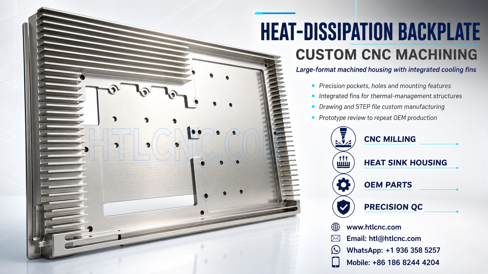
Custom CNC machining for large heat-dissipation backplates with integrated fins, precision pockets, mounting holes and OEM production support from drawings and STEP files.
Large equipment backplates can combine structural support, component mounting and thermal-management features in one machined part. The component shown here has a broad recessed central area, dense perimeter fins, multiple hole patterns, pockets, cutouts and mounting interfaces. These features must remain aligned to the drawing while the part is supported through heavy material removal and finishing operations.
HTL CNC manufactures custom heat-dissipation backplates, large machined housings and equipment mounting structures from customer drawings, STEP files and approved samples. We support prototype review, low-volume validation and repeat OEM production. The exact material, alloy grade, tolerances, surface finish and thermal requirements are always defined by the customer's engineering documents.
Integrated Cooling Fins and Large-Format Geometry
Machined fins can increase external surface area and may form part of a customer's thermal-management design. Their final performance depends on the complete assembly, including heat-source position, contact interfaces, airflow, fin orientation and operating environment. Manufacturing therefore follows the validated customer design rather than making assumptions from appearance alone.
Long fins and large planar areas can be sensitive to cutting force, vibration and uneven material removal. Process planning may use staged roughing, balanced material removal and controlled finishing passes to help maintain stability. Tool reach, chip evacuation and access between fins must also be considered before the production route is released.
Precision Pockets, Holes and Mounting Features
The backplate contains multiple pockets, through-holes, counterbored or recessed features, elongated openings and raised mounting interfaces. Their positional relationships can affect installation of electronic modules, brackets, covers or adjacent assemblies. Datum selection and fixture design should therefore be based on the functional drawing rather than the outer profile alone.
Depending on part size and feature access, the process may combine 3-axis milling with controlled reclamping, 4-axis indexing or 5-axis machining. Multi-axis access can reduce repeated setups for side features and angled interfaces, but the selected route must remain appropriate to the specified geometry, tolerance and production quantity.
Controlling Flatness, Wall Stability and Burrs
Large recessed regions and repeated fins create uneven stiffness across the component. Clamping must hold the part securely without forcing it away from its natural free-state geometry. Roughing and finishing sequences should leave stable support around critical surfaces until the correct stage of production.
Deburring is important around fin edges, intersecting holes, slots and mounting openings. If the customer identifies cosmetic faces, sealing surfaces, thermal-contact regions or protected assembly areas, these requirements should be included in the RFQ so handling and finishing can be planned before machining begins.
Inspection and Surface-Finish Planning
Inspection can focus on functional datums, hole positions, pocket depths, mating surfaces, fin geometry, threads and critical face relationships. Depending on the approved quality plan, verification may use calipers, micrometers, gauges, height measurement and CMM inspection. Large parts may require a defined inspection sequence to confirm both local features and relationships across the complete component.
The part can be supplied with an as-machined surface or a customer-specified finish appropriate to the selected material. Brushing, blasting, anodizing, plating, passivation, painting or another approved treatment may be considered when defined by the drawing. Masking, coating allowance, thread protection and thermal-contact areas should be confirmed before quotation.
From Prototype Review to Repeat OEM Production
Prototype machining helps engineering teams verify assembly fit, component mounting, interface relationships and inspection methods before repeat quantities are released. After approval, controlled programs, repeatable fixtures, revision management and documented inspection points support stable OEM production.
For an engineering review and quotation, send your 2D drawing, STEP file, specified material, quantity, critical tolerances, inspection requirements and surface-finish notes.
Website: www.htlcnc.com Email: htl@htlcnc.com WhatsApp: +1 936 358 5257 Mobile: +86 186 8244 4204
Have a part ready for engineering review?
Send your drawing, STEP file, material and quantity directly to HTL CNC for a manufacturing quotation.