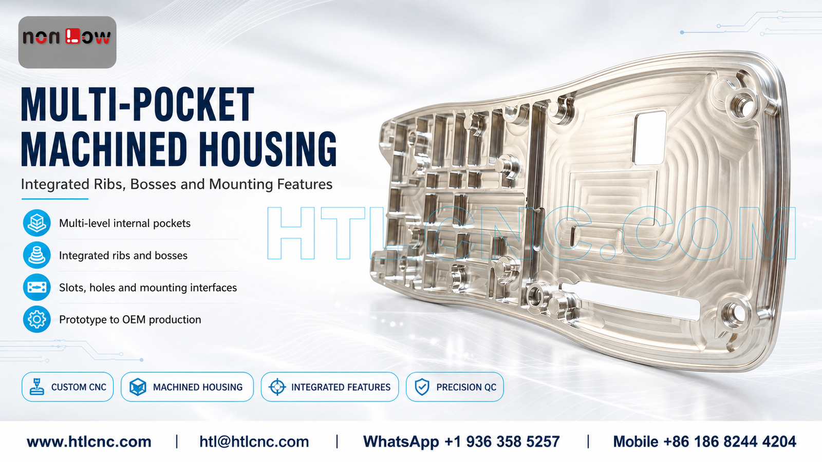
Drawing-based CNC manufacturing for multi-pocket housings with integrated ribs, bosses, slots, openings and mounting interfaces from prototype to OEM production.
A multi-pocket machined housing can combine deep and shallow cavities, reinforcing ribs, raised bosses, long slots, local openings and mounting interfaces within one structural component. The housing shown here contains a broad machined interior with feature density that changes significantly from one end to the other. This geometry requires a machining plan that balances material removal, access, stiffness and inspection.
HTL CNC manufactures custom multi-pocket housings, structural frames and integrated-feature components from customer drawings, STEP files and approved samples. We support engineering prototypes, low-volume validation and repeat OEM production. Material, dimensions, tolerances, finish and final application must always follow the customer's approved technical documents.
Multi-Level Pocket Machining
The visible housing includes pockets at several depths, separated by walls, ribs and local platforms. Process planning should identify which areas can be rough machined with larger tools and which require smaller cutters for narrow channels, local corners or residual material. Pocket depth, internal corner radius, tool reach and chip evacuation should be reviewed together.
A controlled roughing sequence can remove bulk material while leaving enough support around walls and bosses. Finishing allowances should be selected according to the specified material, geometry and drawing requirements. Rest machining may be used where a smaller tool must remove material left by a larger cutter, but the approved model should remain the authority for every feature.
Integrated Ribs and Structural Stability
Ribs can increase local stiffness without requiring the entire housing to remain thick. During machining, however, the remaining structure changes as surrounding material is removed. Narrow ribs may become sensitive to vibration or tool pressure, especially when adjacent pockets are deep or interrupted.
Tool engagement and cutting direction should be planned to reduce unnecessary loading on slender features. Fixtures must hold the workpiece securely without forcing broad surfaces or thin walls away from their free-state condition. Balanced roughing and controlled final passes can help manage distortion as the part approaches its finished geometry.
Bosses, Bores and Mounting Interfaces
Raised bosses provide local surfaces for holes, threads, fasteners or assembly interfaces. Their position, height and relationship to the selected datums may be more important than their cosmetic appearance. Drawing review should identify critical bosses, precision bores and threaded features so the machining and inspection plans prioritize functional relationships.
Material around a boss should be removed in a sequence that protects support and access. Where close-positioned bores or threads are specified, tool clearance, chip evacuation and gauge access should be confirmed before production. Edge breaks and deburring must be controlled so functional diameters and mating faces are not altered.
Slots, Openings and Feature Access
The housing also includes rectangular openings, long slots and features positioned close to the perimeter. These details may require different tool orientations or controlled reclamping. Depending on the released geometry, the manufacturing route may use 3-axis milling, 4-axis indexing, 5-axis machining or a combination of operations.
Reducing unnecessary setups can help maintain relationships between pockets, bosses and side features. However, the best route depends on part size, fixture clearance, cutter reach, datum structure, tolerance requirements and production quantity. A complex appearance alone does not establish a specific process or tolerance.
Workholding and Datum Planning
An irregular housing needs stable locating surfaces and a clear datum strategy. Initial operations may establish reference faces before internal pockets and detailed features are machined. Later setups should reproduce the agreed datum relationships without excessive clamping force.
Support points should remain clear of toolpaths, critical surfaces and cosmetic zones. Where the finished component has limited flat contact area, custom fixtures or soft jaws may be needed. The manufacturing team should also consider how the part will be released, handled and measured without marking finished edges or deforming thin sections.
Surface Treatment and Deburring
The component may be supplied as machined or prepared for a customer-specified treatment compatible with the specified material. Anodizing, plating, passivation, blasting, brushing, polishing, painting or another finish should be considered only when defined by the drawing. Coating allowance, masking zones, thread protection and cosmetic requirements should be confirmed before quotation.
Multi-pocket housings contain many intersecting edges and recessed areas. Deburring should remove sharp material without changing pocket dimensions, boss heights, hole diameters or specified edge conditions. Cleaning and packaging may also require attention because chips or media can remain in deep pockets and threaded holes.
Inspection for Integrated-Feature Housings
Verification may include overall profile, pocket depths, wall thicknesses, rib locations, boss heights, bore diameters, thread checks, slot positions, mating faces and datum-based feature relationships. Calipers, micrometers, height measurement, pin or thread gauges, optical equipment and CMM inspection may be used according to the agreed quality plan.
Inspection should focus on features that control assembly and function. The drawing should identify critical dimensions and geometric requirements so measurement resources are applied appropriately. Prototype production can help confirm assembly fit, machining access, inspection methods and surface requirements before repeat quantities are released.
Prototype to OEM Production
Early prototypes allow engineering teams to review pocket geometry, mounting interfaces, wall stability and finishing requirements. After approval, controlled programs, repeatable fixtures, revision management and documented inspection points support stable low-volume and OEM manufacturing.
For engineering review and an RFQ, send your 2D drawing, STEP file, specified material, quantity, critical tolerances, inspection requirements and surface-finish notes.
Website: www.htlcnc.com Email: htl@htlcnc.com WhatsApp: +1 936 358 5257 Mobile: +86 186 8244 4204
Have a part ready for engineering review?
Send your drawing, STEP file, material and quantity directly to HTL CNC for a manufacturing quotation.