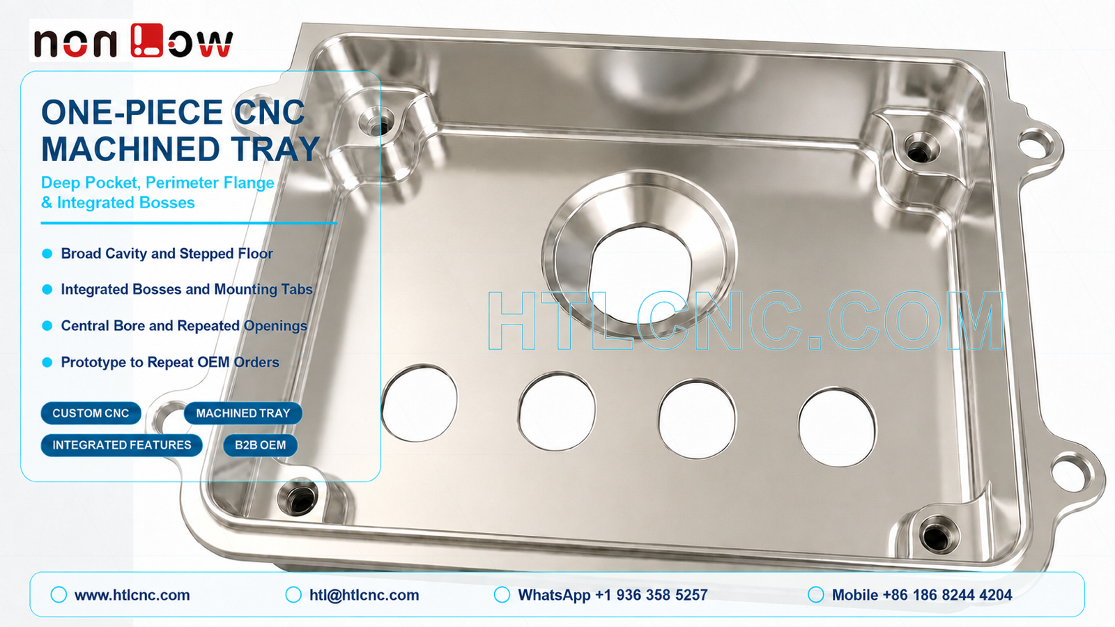
B2B custom CNC manufacturing for one-piece machined trays with broad cavities, perimeter flanges, integrated bosses, mounting tabs and repeated openings.
A one-piece CNC machined tray can combine a broad internal cavity, perimeter flange, integrated corner bosses, mounting tabs, a central bore and repeated openings within a single component. The visible part has a large machined floor surrounded by raised walls and multiple features that must remain related to the same datum structure. This type of geometry requires more than removing material from a rectangular blank: process planning must consider rigidity, pocket access, feature relationships, edge quality and inspection from the first setup.
HTL CNC manufactures drawing-based machined trays, housing bases and custom structural components for overseas OEMs, product-development companies, equipment builders and contract manufacturers. We support engineering prototypes, low-volume validation and repeat B2B orders. Material, dimensions, tolerances, finish and final application must follow the customer's released drawing and STEP model rather than assumptions based on appearance.
B2B Project Review Before Quotation
For a procurement team, a useful quotation should reflect the actual technical and commercial scope. The RFQ package should include the 3D model, 2D drawing, specified material, quantity or annual demand, critical tolerances, threads, surface treatment, inspection documents, packaging requirements and delivery destination. This information allows the machining supplier to review stock size, machine travel, fixture strategy, tooling, cycle time and quality requirements on the same basis used for supplier comparison.
Engineering and sourcing teams may also need drawing confidentiality, revision control, sample quantities, first-article expectations and a clear transition from prototypes to repeat purchase orders. These requirements should be identified before production so programs, fixtures and inspection records remain linked to the approved revision. A complete RFQ reduces the risk of receiving a generic price that does not include the required quality or delivery scope.
Broad Cavity and Stepped Floor Machining
The tray contains a large recessed area with local changes in floor height and surrounding walls. Rough machining should remove bulk material while preserving enough support for the flange, bosses and floor. Tool diameter, pocket depth, internal corner radius, cutter reach and chip evacuation should be reviewed together.
A larger cutter may remove open areas efficiently, while smaller tools finish local corners, boss transitions and residual stock. The process should avoid concentrating cutting force on unsupported walls or thin floor regions. Finishing allowances and toolpaths must be selected according to the specified material and drawing requirements; no tolerance should be inferred from the product photograph.
Perimeter Flange and Mounting Tabs
The outside flange and mounting ears create the primary boundary of the component. Their hole positions, face condition and relationship to the internal cavity may control assembly with another part, frame or cover. The drawing should identify functional datums, hole requirements and any flatness, profile or positional tolerances needed for assembly.
Because the perimeter becomes less rigid as the cavity is opened, clamping force and support location require attention. Excessive pressure can temporarily flatten or twist the component during machining, allowing it to move after release. Fixtures should locate the tray repeatably while supporting the structure without masking its free-state condition.
Integrated Bosses and Local Features
Raised bosses inside the tray provide local surfaces for holes, threads, fasteners or other drawing-defined interfaces. Boss height, bore diameter, thread condition and location relative to the selected datums can be more important than the surrounding cosmetic surface. Machining should leave sufficient support around each boss while adjacent material is removed.
The visible component also includes local corner platforms and transitions between the wall, floor and bosses. These areas may require smaller tools and controlled tool engagement. Deburring must remove sharp material without changing boss height, bore size, thread entry or drawing-defined edge conditions.
Central Bore and Repeated Openings
The large central opening and row of repeated circular openings introduce additional positional relationships. Depending on diameter, depth and tolerance, a bore may be drilled, interpolated, bored, reamed or finished by another approved method. The process route should be selected from the drawing rather than from appearance alone.
Repeated openings should remain consistent in size, spacing and edge quality. If their position relative to the flange or internal bosses is critical, machining and inspection should use the same datum structure. Where an opening passes through a thin floor or intersects another feature, tool exit, burr control and support should be considered during programming.
3-Axis, 4-Axis and 5-Axis Process Selection
A tray with mainly accessible top-side features may be suitable for 3-axis CNC milling followed by controlled secondary operations. Side holes, angled interfaces or features distributed around the perimeter may require indexed setups, 4-axis machining or 5-axis access. More axes do not automatically produce a better result; the correct route depends on feature access, setup stability, datum relationships and production quantity.
For repeat OEM orders, process selection should also consider fixture repeatability and inspection efficiency. A stable multi-setup route can be preferable to a complicated single setup when it provides better support and clearer control of critical features. Prototype manufacturing helps confirm the route before larger quantities are scheduled.
Distortion Control and Workholding
Removing a broad cavity changes the stiffness and internal stress balance of the stock. A practical sequence may establish reference faces first, rough the pocket in balanced stages and reserve controlled finishing passes for the floor, walls, flange and critical interfaces. The exact approach depends on material, stock condition and released tolerance requirements.
Soft jaws, fixture plates or custom supports may be used where standard clamps cannot reach suitable locating areas. Contact points should remain clear of cutting paths, critical faces and cosmetic surfaces. The part should be handled and measured after release so inspection reflects its actual condition rather than a clamped state.
Inspection for Supplier Approval and Repeat Orders
Inspection may include overall profile, flange dimensions, cavity depth, floor levels, boss height, bore diameter, thread checks, repeated-hole spacing, mounting-hole positions and relationships to drawing datums. Calipers, micrometers, height measurement, gauges, optical equipment and CMM inspection may be used according to the agreed quality plan.
B2B customers should define the documentation expected with samples and repeat deliveries. This may include a first-article report, dimensional results for selected characteristics, material or finishing documents supplied by the relevant source, or batch inspection records when agreed in the purchase order. Requirements must be confirmed before quotation because documentation scope affects inspection time and delivery planning.
Surface Finish, Cleaning and Export Packaging
The tray may be supplied as machined or prepared for a customer-specified treatment compatible with the approved material. Anodizing, plating, passivation, blasting, brushing, polishing, painting or another finish should be applied only when defined by the drawing. Coating allowance, masking, thread protection and cosmetic acceptance criteria should be reviewed before production.
Broad cavities, blind areas and threaded holes require controlled cleaning so chips or finishing media do not remain in the component. Visible surfaces may need protective separation and export packaging to reduce contact marks during storage and transport. Packaging standards, labeling and delivery destination should be included in the RFQ when they affect the commercial scope.
Prototype Validation to Repeat B2B Production
Prototype quantities allow engineering teams to check assembly fit, flange condition, boss locations, opening alignment, edge quality and finish requirements. Procurement teams can use the same stage to evaluate response time, documentation, communication and delivery performance before adding a supplier to a repeat-order program.
After approval, controlled programs, repeatable fixtures, documented inspection points, revision management and purchasing forecasts support stable low-volume ramp-up and OEM production. Customers should communicate expected order frequency or annual demand when available so capacity, material purchasing and lead-time planning can be reviewed realistically.
For a manufacturing and commercial review, send your 2D drawing, STEP file, specified material, target quantity or annual demand, critical tolerances, inspection requirements, surface-finish notes, packaging requirements and delivery destination.
Website: www.htlcnc.com Email: htl@htlcnc.com WhatsApp: +1 936 358 5257 Mobile: +86 186 8244 4204
Have a part ready for engineering review?
Send your drawing, STEP file, material and quantity directly to HTL CNC for a manufacturing quotation.