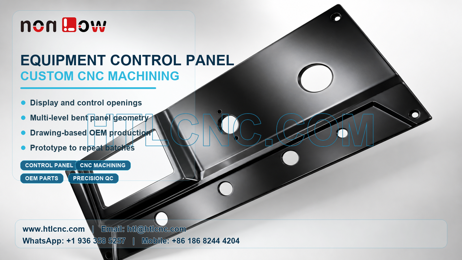
B2B drawing-based CNC manufacturing for black equipment control panels with a display window, multiple control openings, formed levels and repeat OEM production support.
A custom equipment control panel brings display, switch, indicator and mounting interfaces together in one visible component. The panel shown here has a large rectangular display opening, a prominent circular opening, several smaller round control openings, corner mounting holes and formed transitions between different levels. Its dark finished surface also makes edge quality, handling marks and visual consistency important during supplier review.
HTL CNC supports drawing-based custom CNC machining for overseas OEMs, product-development companies, equipment manufacturers, contract manufacturers, engineers and purchasing teams. Projects can move from prototype verification through low-volume ramp-up to repeat B2B orders. The exact material, dimensions, tolerance, coating and final application must follow the customer's released drawing, STEP model and approved sample; none of these should be inferred from a photograph.
B2B RFQ and Supplier Introduction
A useful quotation begins with a complete engineering and commercial package. Buyers should provide a 3D model, 2D drawing, specified material, prototype quantity, expected batch size or annual demand, critical dimensions, cosmetic requirements, surface-treatment notes, inspection documentation, packaging needs and delivery destination. With this information, a machining supplier can review stock condition, process access, setup count, fixture strategy, inspection time and lead-time planning against a clearly defined scope.
Supplier onboarding may also include confidentiality requirements, revision control, sample approval criteria and designated communication between engineering and procurement. Programs, workholding references and inspection records should remain linked to the approved drawing revision. When a display size, button layout or mounting interface changes, the updated files should be released before the next batch begins.
Display Window and Perimeter Control
The rectangular opening is a dominant visible feature. Its length, width, internal corner radius and position relative to the panel perimeter may affect fit with a customer-specified display, bezel or adjacent assembly. The drawing should state the required edge condition and any profile or positional control that matters to assembly.
Milling the opening requires a tool diameter compatible with the approved internal corner radius. Entry strategy, cutter reach, support behind the panel and finishing passes should be selected to reduce burrs and protect the surrounding cosmetic surface. If a perfectly sharp internal corner is functionally required, the RFQ should identify the secondary process or design allowance rather than assuming it can be created by ordinary end milling.
Circular Control and Indicator Openings
The visible face includes one large circular opening, smaller round holes and a row of control locations on the lower formed section. These features may support switches, indicators, fasteners or other customer-defined interfaces, but their exact use must be confirmed from the assembly documentation. Diameter, position, spacing, depth and edge-break requirements should be dimensioned from a stable datum structure.
Depending on the released requirements, circular features may be drilled, interpolated, bored, reamed or finished through another approved method. Closely related hole patterns should be programmed and inspected from common datums so their positions remain consistent with the display opening and exterior edges. Deburring must remove sharp material without enlarging the holes or rounding a functional seating surface.
Formed Levels, Bends and Datum Strategy
This component contains multiple planes connected by bends or formed transitions. A drawing-based production plan needs to distinguish features that are machined before forming from those completed after the panel reaches its final shape. Bend location, angle, inside radius and springback allowance can influence the final relationship between openings on different planes.
If the panel is supplied as a pre-formed blank, fixtures must locate it without forcing the part away from its natural geometry. If machining and forming are both included in the supplier scope, engineering review should establish the sequence and define which datums control finished inspection. Features on separate planes may require indexed positioning, controlled reclamping or multi-axis access according to the drawing.
Workholding and Cosmetic Surface Protection
A broad finished panel can be sensitive to local clamp pressure and contact marks. Supports should hold stable regions while keeping cutting paths accessible. Protective interfaces may be required where fixture contact could damage a customer-facing surface. Excessive clamping can temporarily distort the panel and create misleading measurements while it remains in the fixture.
The manufacturing route should also protect the dark surface during transfer, inspection, cleaning and packaging. Cosmetic zones, allowable marks, gloss or texture range and masking requirements should be defined by the customer. The component may be machined before treatment or supplied with a drawing-specified finish, depending on material and process compatibility. Anodizing, plating, painting, passivation, brushing, blasting or another treatment should never be assumed without the released specification.
Inspection for Display, Button and Mounting Interfaces
Verification may include overall profile, display-window size and position, circular-opening diameters, hole spacing, bend relationships, mounting-hole locations and any drawing-defined flatness or profile requirements. Calipers, micrometers, height measurement, pin gauges, optical equipment and CMM inspection may be used according to feature size and the agreed quality plan.
For B2B supplier approval, the customer should state which records are required with prototypes and repeat deliveries. The scope may include selected dimensional results, a first-article report, material or finishing documents from the relevant source, or batch inspection records. Documentation requirements affect inspection time and quotation, so they should be agreed before supplier nomination.
Prototype Validation and Repeat OEM Orders
Prototype quantities allow engineering teams to verify display fit, control alignment, edge condition, bend relationships, visual quality and assembly clearances. Procurement teams can use the same stage to evaluate communication, revision handling, documentation and delivery performance before releasing recurring purchase orders.
After sample approval, controlled programs, repeatable workholding, defined inspection points and version management support low-volume ramp-up and stable repeat production. Forecasts or annual demand help the supplier plan material purchasing, machine capacity, batch size, protective packaging and lead time. Clear purchase-order revisions reduce the risk of producing obsolete panel geometry.
For an engineering and commercial review, send your 2D drawing, STEP file, specified material, prototype and production quantities, annual demand, critical tolerances, inspection requirements, surface-finish notes, packaging requirements and delivery destination.
Website: www.htlcnc.com Email: htl@htlcnc.com WhatsApp: +1 936 358 5257 Mobile: +86 186 8244 4204
Have a part ready for engineering review?
Send your drawing, STEP file, material and quantity directly to HTL CNC for a manufacturing quotation.