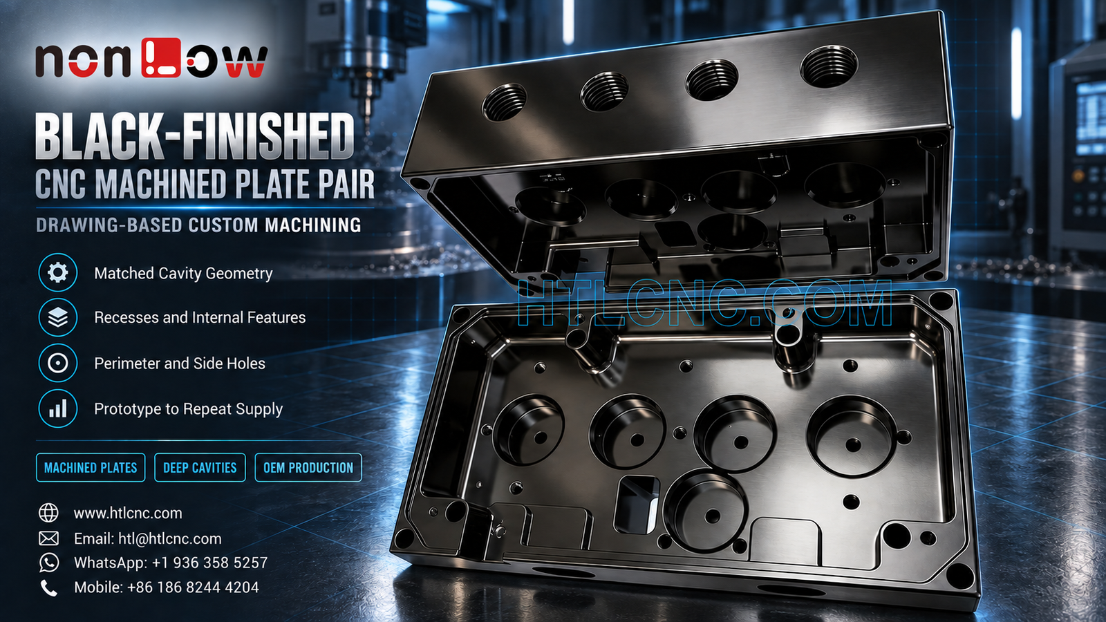
A black-finished CNC machined plate pair requires coordinated cavity geometry, circular recesses, perimeter interfaces, side threads and finish-aware inspection for repeat OEM assembly.
A black-finished CNC machined plate pair can require tighter coordination than two unrelated parts because their cavities, circular recesses, perimeter steps, mounting holes and side interfaces may need to work together in one assembly. The photograph shows two rectangular machined plates presented as an open pair. Both contain broad internal recesses, repeated circular features, local pockets and perimeter holes, while the upper plate visibly includes four threaded side openings. The image does not identify material grade, black-finish process, tolerances, sealing function or final application. Those requirements must come from the buyer's released drawings, STEP models and finish specification. HTL CNC supports overseas OEMs, product-development teams, equipment builders, contract manufacturers, engineers and procurement groups with drawing-based custom CNC machining, prototype validation, low-volume ramp-up and repeat production.
Why a Paired-Part RFQ Needs Interface Definition
Two parts that appear to belong together should not be quoted from visual similarity alone. The RFQ must identify each part number, revision and orientation, then show which faces, holes, pockets or circular features interact. If the parts share a common assembly datum, the drawing package should state it directly rather than relying on independent edge dimensions.
An assembly model can help the supplier review closure, internal clearance, fastener access and interface alignment without guessing the product's purpose. Where the plates are not actually a mating pair, the buyer should still separate their requirements so inspection evidence from one component is never applied to the other.
Matched Cavity Geometry and Datum Strategy
The visible cavities contain multiple levels, perimeter walls and local recesses. A useful datum scheme normally starts from stable seating surfaces and locating features, then controls important internal geometry from those references. The exact scheme must follow functional requirements on the released drawing.
Workholding should support broad faces without distorting thin wall regions or blocking features needed in later operations. If both plates share related interface dimensions, the machining and inspection plans should use a consistent reference logic while preserving separate part-number control. HTL's custom CNC machining service applies drawing-led process selection across related components and variants.
Circular Recesses, Internal Posts and Local Pockets
The lower plate visibly includes four larger circular recesses and a fifth circular feature near the center-lower region, each with a smaller central hole. Additional internal posts, smaller holes and rectangular pockets are distributed around the cavity. The upper plate includes a different but related arrangement. The photograph cannot establish the function of any feature.
Drawings should define recess diameter and depth, central-hole size, boss or post height, local pocket geometry and positional relationships. Tool access, wall thickness and cutter reach should be reviewed together. Internal corners normally retain a cutter radius unless another manufacturing method is specified. Deburring must not enlarge central holes or round locating steps beyond the released edge requirements.
Four Threaded Side Openings and Multi-Face Machining
Four threaded openings are visible along one side of the upper plate. Their thread standard, effective depth, pitch, entry chamfer and position cannot be determined from the image. These details should be stated explicitly, together with any requirement for thread gauges or customer-approved functional checks.
Side features may require controlled refixturing, indexed 4-axis positioning or 5-axis CNC machining, depending on access, rigidity, tolerance and quantity. Machine-axis count does not replace datum transfer. The process plan should explain how side-thread positions remain linked to the main cavity and mounting interfaces.
Black Finish: Appearance Is Not a Process Specification
A black surface can result from several different processes, but the photograph does not prove which one was used. The buyer should provide the exact finish specification, approved color reference, gloss or texture range, cosmetic zones, masking requirements, coating allowance and certification scope. HTL will not infer a coating process from color alone.
Threads, close-fit holes, seating surfaces and electrical or sealing interfaces may need masking or post-finish verification. The drawing should state whether dimensions apply before or after finishing. A physical limit sample can help align visual acceptance when shade or surface appearance matters.
Inspection of the Pair as Components and as an Assembly
Each plate needs its own dimensional record, identified by part number and revision. Risk-based inspection may include outside profile, cavity depths, circular-feature sizes and positions, perimeter-hole patterns, side-thread location, face relationships, flatness or profile only where specified. Calibrated hand tools, depth and height systems, pin or thread gauges, optical equipment and CMM inspection may be combined according to feature access and tolerance.
If the two plates interact, dimensional inspection may be supplemented by a customer-approved assembly check. This can confirm alignment, clearance, closure and fastener access, but it should not replace drawing-based acceptance unless the buyer defines a functional gauge or assembly criterion.
Prototype Qualification and Engineering Changes
Prototype builds allow the engineering team to verify matched interfaces before committing to repeat quantities. Reviews may cover cavity clearance, circular-feature alignment, side-thread access, edge condition and black-finish appearance. Any resulting geometry or finish change should update the 2D drawing, STEP model and configuration record together.
After approval, controlled programs, qualified fixtures, approved finish sources, first-piece checks and formal revision control support low-volume ramp-up and recurring orders. HTL's prototype and low-volume CNC machining service supports this staged qualification route.
Preventing Pairing and Revision Mix-Ups
Related components create a specific logistics risk: an acceptable plate can be packed with the wrong mating revision or finish version. Labels should show part number, revision, quantity and production lot. When pairs must remain together, the purchase order should define pairing, serialization or kit-label requirements.
Packaging should separate black cosmetic faces from metal-to-metal contact. Protective sleeves, films, separators or formed trays may be selected from the actual finish and geometry. Annual demand, release frequency, destination and target schedule help the supplier plan material, machining, finishing, inspection and export packing.
Supplier Qualification and Drawing Confidentiality
OEM buyers should confirm how a supplier controls customer files, grants model access, separates obsolete revisions and protects confidential drawings. A sourcing review may also cover machine capacity, inspection availability, outside-process control and corrective-action records. Where required, establish the NDA and secure file-transfer process before releasing complete design data.
Repeat-order consistency depends on traceable inputs as much as machine capability. Material lot, finish batch, program revision, inspection record and shipment identification should remain connected to the correct component throughout production.
RFQ Checklist for a Black-Finished CNC Machined Plate Pair
Send the released 2D drawing and STEP file for each component, part numbers and revisions, assembly model where applicable, exact material specification, black-finish standard, prototype and production quantities, annual demand, functional datums, cavity and circular-feature requirements, thread definitions, tolerances, cosmetic and masking zones, inspection-document scope, pairing or kit requirements, packaging, destination and delivery schedule. HTL CNC can then review the black-finished CNC machined plate pair and propose a controlled machining, finishing, inspection and repeat-supply plan.
Website: www.htlcnc.com Email: htl@htlcnc.com WhatsApp: +1 936 358 5257 Mobile: +86 186 8244 4204
Have a part ready for engineering review?
Send your drawing, STEP file, material and quantity directly to HTL CNC for a manufacturing quotation.