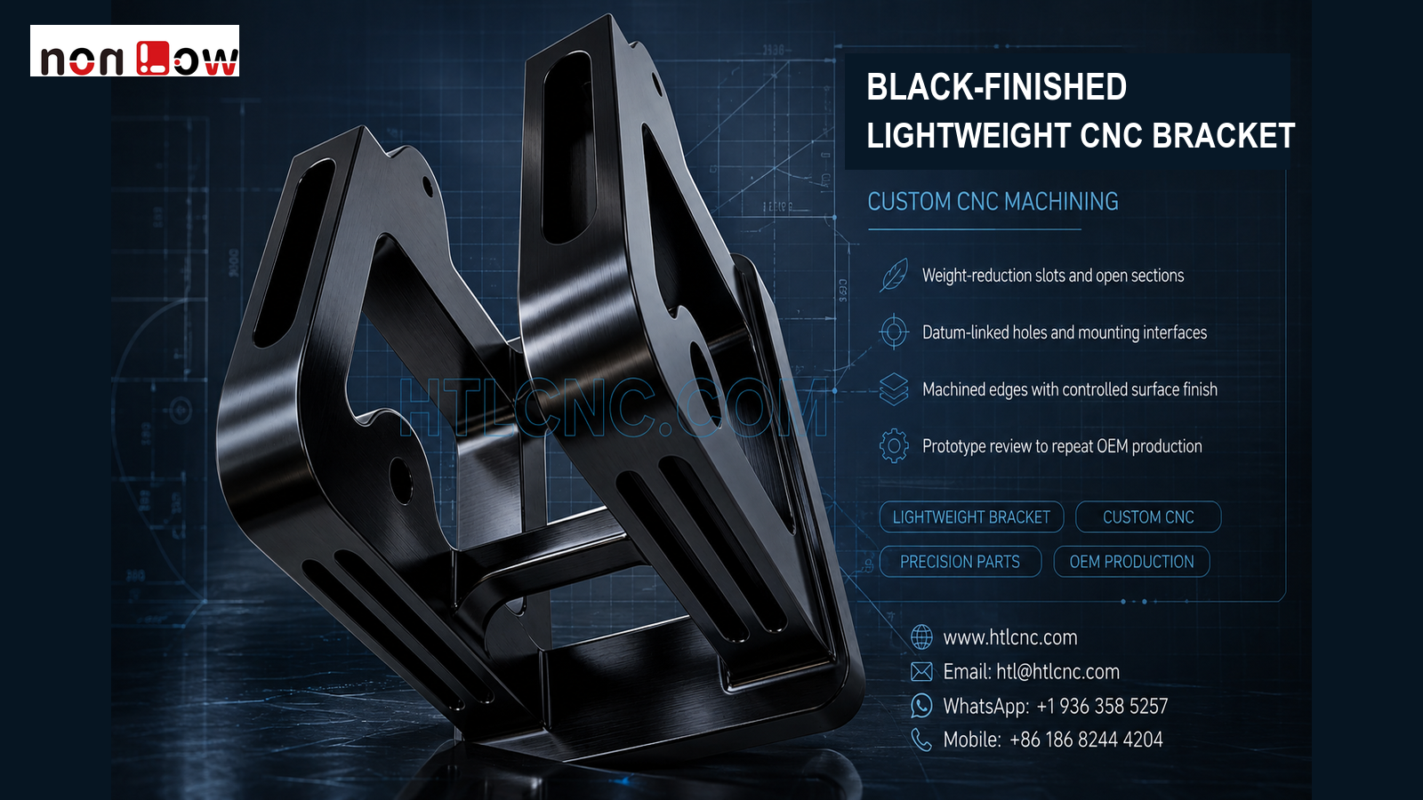
Black-finished lightweight CNC bracket machining combines large relief slots, open sections, multi-plane mounting holes and protected cosmetic surfaces in one controlled OEM process.
Black-finished lightweight CNC bracket machining is relevant when an OEM structural component combines broad side frames, long weight-reduction slots, open triangular regions, cross-members and holes on several planes. The pictured part visibly shows two connected side structures with machined edges, elongated openings, circular mounting features and a dark surface condition. HTL CNC supports overseas equipment builders, product-development companies, automation teams, engineers and procurement groups with custom CNC machining, precision CNC parts, multi-face milling, prototypes, low-volume production and repeat drawing-based manufacturing. The image does not confirm the material grade, coating type, tolerance, load rating or final use; those requirements must be defined by the customer's released 2D drawing, STEP model and finish specification.
What Must an OEM Define for a Lightweight Bracket?
A lightweight bracket is not qualified by appearance alone. Buyers should identify the load paths, functional mounting faces, locating holes, fastener clearances, permitted flex and interfaces to adjacent components. Large windows and slots may reduce mass, but only the customer's engineering data can establish whether each opening is structural, cosmetic or intended for access.
The RFQ should distinguish controlled datums from general profile surfaces. This lets the supplier concentrate machining and inspection effort on the relationships that affect assembly instead of applying unnecessary tolerances to every edge.
Long Slots, Open Sections and Remaining Stiffness
The visible side frames contain long narrow slots and large open regions. As material is removed, the remaining webs and cross-members can become more sensitive to clamping force, cutting load and heat. A practical route may leave temporary support during roughing, balance stock removal between related areas and finish critical faces after the main structure has stabilized.
Internal corner radii and slot width affect cutter selection and tool reach. Larger practical radii generally allow stronger tools, while narrow deep transitions may require smaller cutters and additional passes. Any sharp internal corner with a functional purpose should be identified explicitly on the drawing.
Datum Planning Across Two Side Frames
The connected geometry requires more than checking the two sides independently. Mounting holes and machined faces may need to remain related across the bracket width, and the cross-members may establish spacing or orientation. The released drawing should define the primary seating plane, secondary direction and the features used to locate the assembly.
Depending on access, quantity and tolerance, the route may use qualified 3-axis refixturing, indexed 4-axis work or 5-axis CNC machining. The objective is to reduce uncontrolled datum transfer and maintain feature relationships, not simply to maximize axis count.
Hole and Edge Control for Assembly
Circular holes are visible on the broad faces and side regions. The RFQ should identify locating holes, clearance holes, threaded features and any counterbore or spotface requirements. Hole size alone is not sufficient when two interfaces must align; position, perpendicularity or spacing may be the functional characteristic.
The many open edges also require a controlled deburring plan. Loose burrs should be removed without rounding a datum, thinning a web or altering a drawing-defined edge. Customer-defined edge-break limits and protected surfaces prevent subjective acceptance decisions.
Surface Finish Without Guessing the Coating
The photograph shows a dark finished appearance, but it does not prove black anodizing, paint, plating, oxide or another process. Material, service environment, conductivity, wear, corrosion, appearance and dimensional allowance must be reviewed before selecting a finish.
Close-fit holes, threads and seating faces may need masking, pre-finish allowance or post-finish verification. Cosmetic zones should be identified on the drawing, and the approved sample should define acceptable shade, texture and handling marks when appearance is important.
Inspection Evidence for Supplier Qualification
A risk-based inspection plan may cover datum-face condition, bracket width, side-frame parallelism, slot size and position, cross-member spacing, mounting-hole diameter and location, edge condition and drawing-defined geometric controls. Measurement may combine calibrated hand tools, height systems, pin or thread gauges, optical inspection, CMM probing and customer-approved fixtures according to access and tolerance.
First-article documentation should identify the part number, drawing revision, material and finish records when requested, measurement method and production lot. Repeat supply benefits from controlled programs, qualified fixtures, first-piece approval, finish-lot traceability and formal revision control.
Prototype Validation Before Repeat OEM Production
Prototype quantities allow the OEM team to verify mounting alignment, adjacent-part clearance, fastener access, bracket spacing, finish appearance and the proposed inspection method. Load, vibration, fatigue or life testing requires customer-defined conditions and acceptance criteria; no performance claim can be made from the photograph.
After sample approval, HTL's prototype and low-volume CNC machining supports a controlled ramp from engineering samples to pilot quantities. The custom CNC machining service can then support repeat production with revision management, lot records, protected export packaging and delivery planning.
RFQ Checklist for a Lightweight CNC Bracket
Send the released 2D drawing, STEP file and relevant assembly model. Include material, prototype quantity, production quantity or annual demand, functional datums, controlled slots and holes, edge requirements, tolerances, finish specification, cosmetic zones, inspection-document scope, revision status, packaging, destination and target schedule. HTL CNC can then review the black-finished lightweight CNC bracket machining project and prepare a manufacturing, quality and supply plan.
Website: www.htlcnc.com Email: htl@htlcnc.com WhatsApp: +1 936 358 5257 Mobile: +86 186 8244 4204
Have a part ready for engineering review?
Send your drawing, STEP file, material and quantity directly to HTL CNC for a manufacturing quotation.