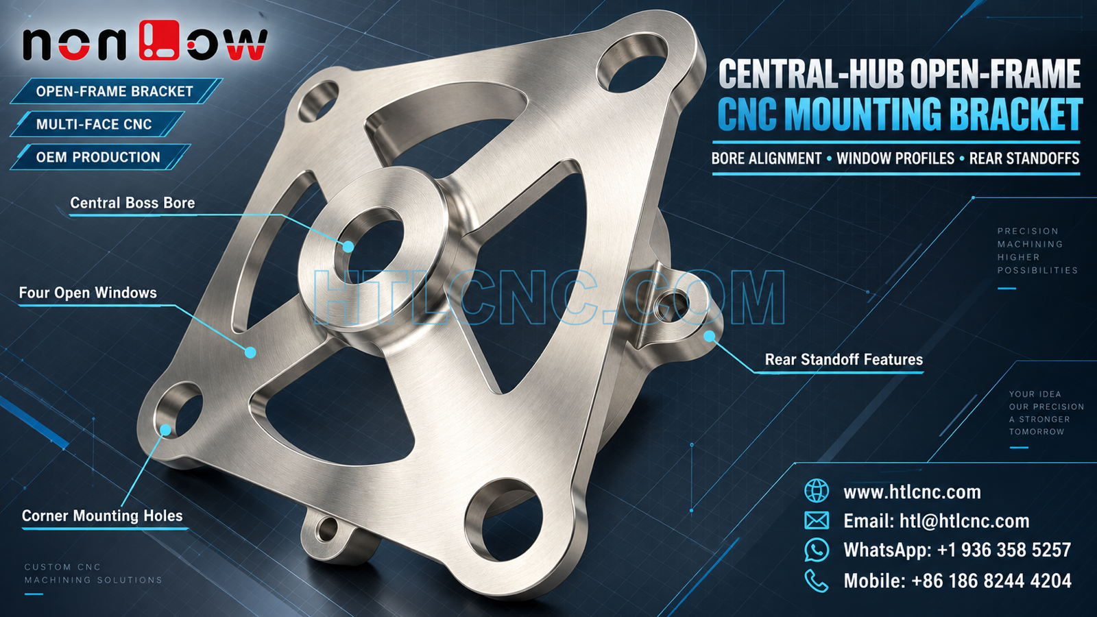
A central-hub open-frame CNC mounting bracket combines a raised boss bore, four large windows, corner mounting holes and rear standoff features that require controlled front-to-rear relationships.
A central-hub open-frame CNC mounting bracket combines a raised circular boss and through bore with four large open windows, connecting ribs, corner mounting holes and rear or side standoff features. The pictured part has a compact near-square outline rather than a long rail, so its main sourcing question is how the front hub, frame plane and backside interfaces remain related through machining and inspection. The photograph does not establish the material grade, bore fit, flatness, load requirement, finish or final application. Those requirements must come from the buyer's released drawing, STEP model and assembly specification. HTL CNC supports overseas OEMs and engineering teams with drawing-based custom CNC machining, prototype builds, low-volume ramp-up and repeat supply.
Define the Front-to-Rear Datum Chain Before Quotation
The RFQ should identify which front face, rear standoff face or bore establishes the primary locating condition. A compact open frame can include several surfaces that appear parallel but serve different assembly functions. The drawing should state the datum sequence and specify any perpendicularity, parallelism, position or profile requirements between the front and rear interfaces.
Mating-part data is especially useful when the central boss locates one component while rear standoffs attach another. HTL's custom CNC machining service reviews these relationships before fixture, cutting and inspection plans are selected.
Central Boss Bore Machining and Face Control
The visible hub includes a raised circular face and a through bore. The drawing should define bore diameter, boss diameter and height, face position, transition radii, edge break and any fit or runout requirement. The image does not prove that the bore carries a bearing, shaft or insert.
Depending on stock form, tolerance and batch size, the boss may be turned, bored or circular-milled. What matters is that the chosen route keeps the bore axis and hub face related to the functional frame datum. Measurement may use bore gauges, depth tools, height systems or CMM probing according to the released characteristics.
Rear Standoff Features Need Height and Position Data
Several smaller bosses or feet are visible behind the front frame. Their exact count, heights, hole definitions and functions must be taken from the complete model because the photograph shows them only partially. Each rear feature should have a unique identifier on the drawing and first-article map.
A rear standoff can meet its local diameter while its top face or hole is incorrectly positioned relative to the central boss. The inspection plan should therefore include front-to-rear height, coordinate position and any required coplanarity. If standoffs form an installation plane, that condition should be stated explicitly rather than inferred.
Four Window Profiles and Rib Transitions
Four large windows remove material around the central hub and leave several ribs connecting the hub to the outer frame. The drawing should define window profiles, internal corner radii, rib widths, minimum edge distances and blend transitions where they affect clearance or strength.
Balanced roughing can help preserve support while material is removed. A practical route may establish reference faces, rough opposite windows in a controlled sequence, allow the part to relax, then finish the boss, outer profile and critical windows. The actual sequence depends on material, stock, thickness, tolerance and quantity. Deburring must not thin a rib or change a controlled profile.
Corner Mounting-Hole Alignment
Large mounting holes are distributed around the outer frame, and at least one smaller side or rear hole is also visible. The RFQ should distinguish locating holes, clearance holes, threaded holes and counterbores, then locate every feature from the approved coordinate system.
Individual hole diameters can pass while the pattern is shifted or rotated relative to the hub bore. A risk-based inspection plan should therefore verify both feature size and pattern position. Numbered hole callouts also help procurement and engineering teams trace measurements, deviations and revision changes without ambiguous descriptions.
Multi-Face Machining and Setup Transfer
The front boss, through-windows and outer profile may suit controlled 3-axis milling with boring or circular interpolation. Rear standoffs, side holes and backside surfaces may require refixturing, indexed 4-axis work or 5-axis CNC machining. Machine selection follows the complete model and tolerance stack, not the front photograph alone.
When a second setup is required, qualified faces, purpose-machined locating features or customer-approved fixture datums should transfer the coordinate system. Clamp force should be placed on stable regions and checked after release so the open frame is not accepted only in a fixture-loaded condition.
Inspection Evidence for a Compact Open-Frame Bracket
A first-article report may cover overall profile and thickness, front-face flatness, central bore and boss height, four window profiles, rib widths, corner-hole pattern, rear-standoff heights and locations, backside interfaces and drawing-defined geometric controls. Measurement can combine calibrated hand tools, height systems, pin gauges, optical inspection and CMM equipment.
For supplier qualification, the buyer may also request material documents, finishing records, inspection-equipment identification, traceability and a revision-specific control plan. Drawing confidentiality and obsolete-revision quarantine should be agreed before recurring releases.
Finish Allowance and Protected Handling
The bright metallic appearance does not prove aluminum, stainless steel, plating, anodizing, passivation or polishing. The RFQ should specify the exact material standard and condition, finish process, coating allowance, masking zones, cosmetic criteria and certificate scope. Bore fits, standoff faces, threads and datum surfaces may require masking or post-finish verification.
Open windows, projecting corners and rear bosses can be damaged by impact or metal-to-metal contact. Export packaging may use separators, sleeves, protective film or formed trays selected from the actual geometry and surface requirement. Labels should identify part number, revision, quantity and production lot.
Prototype Fit Checks and Repeat Production
Prototype validation can check hub engagement, frame-face contact, corner-hole alignment, rear-standoff seating, fastener access and clearance through the windows with actual mating components or approved gauges. If loading is relevant, the OEM should define the engineering test and acceptance criteria; no load capacity is inferred from the image.
HTL's prototype and low-volume CNC machining service supports engineering samples before pilot and repeat production. After approval, qualified fixtures, controlled programs, first-piece checks, tool-life rules and revision-specific inspection records help preserve the accepted front-to-rear geometry.
RFQ Checklist for a Central-Hub Open-Frame CNC Mounting Bracket
Send the released 2D drawing and STEP file, mating models and assembly orientation, exact material, prototype and production quantities, annual demand, front and rear datum definitions, central boss and bore requirements, window and rib profiles, corner-hole pattern, rear-standoff details, tolerances, geometric controls, edge breaks, finish, inspection-document scope, packaging, destination and delivery schedule. HTL CNC can then prepare a controlled machining and repeat-supply plan for the central-hub open-frame CNC mounting bracket.
Website: www.htlcnc.com Email: htl@htlcnc.com WhatsApp: +1 936 358 5257 Mobile: +86 186 8244 4204
Have a part ready for engineering review?
Send your drawing, STEP file, material and quantity directly to HTL CNC for a manufacturing quotation.