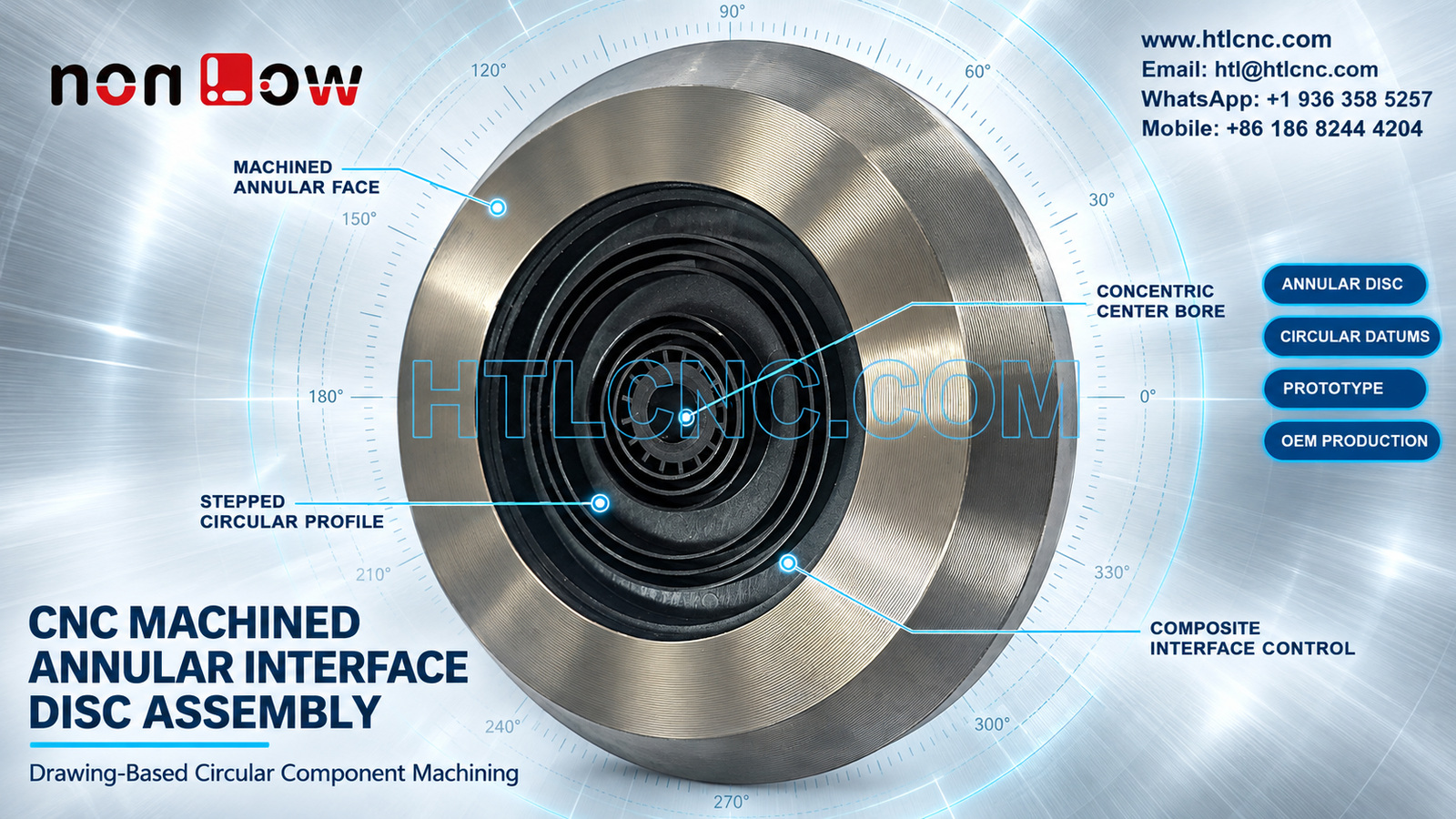
A CNC machined annular interface disc assembly combines a broad circular metal face, concentric stepped geometry, a center bore and a retained dark insert that must remain coordinated through machining, assembly and inspection.
A CNC machined annular interface disc assembly combines a broad machined metal annulus with a dark central insert, several concentric circular features and a center bore. Additional photographs in the source group show a reverse-side radial support structure and retained fasteners. The images do not establish the metal grade, insert material, dimensional tolerances, operating speed, load, friction duty or final application. HTL CNC supports drawing-based circular component machining for overseas OEMs, equipment builders, product-development companies, engineers and procurement teams from prototype review through repeat supply.
Define the Assembly Before Requesting a Machining Quote
A complete RFQ should identify whether the metal annulus is supplied as one finished component or as part of an assembled unit. Buyers should provide the released 2D drawing, STEP files for the complete assembly and each controlled part, bill of materials, mating shaft or housing data, material and finish requirements, prototype and production quantities, annual demand, inspection-document scope, packaging, destination and delivery target.
The assembly drawing should distinguish purchased or molded elements from machined components and identify who is responsible for final assembly. HTL's custom CNC machining service reviews the controlled feature relationships before tooling, workholding and inspection methods are released.
Build the Datum Scheme from the Center Bore Outward
The visible geometry is dominated by concentric circles, but concentric appearance is not measurement evidence. The drawing should identify the functional rotational axis, primary seating face and clocking feature, if one exists. The center bore may establish the axis, yet that choice must come from the actual assembly rather than convenience.
Once the datum structure is defined, the supplier can relate the outer diameter, annular face, internal register, insert location and reverse-side geometry to one coordinate system. This reduces the risk of individually acceptable diameters that do not share the axis required by the mating equipment.
Control the Broad Annular Face for Runout and Contact
A wide metallic face is clearly visible around the dark insert. If this face locates, supports, seals or contacts another component, the drawing may need axial runout, flatness, surface texture and local edge-break requirements in addition to thickness. A bright circular tool pattern is visible, but it does not prove a specified roughness or process.
Face condition should be checked from the released datum axis and after any assembly step that can introduce distortion. When only part of the annulus is functional, the drawing should identify the true contact band so the inspection plan does not impose unnecessary controls on nonfunctional appearance zones.
Treat the Center Bore as an Assembly Interface
The center opening is small compared with the complete disc, which can make access and gauge selection important. Its diameter, depth or through condition, edge treatment and position relative to the primary axis should be explicit. If the bore engages a shaft, bushing or pilot, provide the mating geometry and required clearance or interference.
A plug gauge can confirm size but not necessarily axis relationship. Depending on tolerance, inspection may combine calibrated pin or bore gauges with CMM, roundness or runout measurement. The method should be agreed before the first article when the insert restricts access to the bore.
Specify the Dark Insert Without Assuming Its Material
The photographed assembly contains a dark central element with concentric ribs or rings. The image cannot identify polymer family, elastomer grade, composite formulation, hardness, molding process or functional duty. The bill of materials and component drawing should supply those requirements directly.
The interface between the metal annulus and dark insert may require a register diameter, axial step, retention feature or fastener pattern. Buyers should define allowable gap, seating depth, orientation and inspection condition. If the insert is supplied by the customer, include incoming acceptance criteria and traceability expectations in the sourcing package.
Include Reverse-Side Support Geometry in Process Planning
Source views of the reverse side show radial ribs, a central hub region and several retained fasteners. These features can affect workholding, tool access, balance and final inspection even when the broad front face carries the primary functional requirement. The complete model should therefore include the rear structure rather than representing the product as a simple flat ring.
Fastener type, thread engagement, torque, locking method and responsibility for assembly must come from the released documentation. If the rear insert is molded or purchased, its permissible fixture contact areas should also be identified to prevent damage during machining or verification.
Select the Circular Machining Route from the Tolerance Network
The metal annulus may be produced with CNC turning for coaxial diameters and faces, followed by drilling, milling or another secondary operation for non-rotational features. The qualified route depends on stock form, complete geometry, material, quantity and tolerance relationships; appearance alone cannot prove how the photographed part was made.
HTL's CNC turning and turn-mill machining service evaluates whether the critical face, bore, registers and outer diameter can remain referenced in one controlled setup. If secondary machining is required, the transfer datum and clocking method should be included in the first-article plan.
Inspect the Metal Component Before and After Assembly
Pre-assembly inspection can isolate metal-part dimensions such as outer diameter, bore, shoulder heights, annular-face condition and register geometry. Post-assembly inspection confirms whether insert installation, fastening or handling changed face runout, bore access, seating or overall envelope. Both stages are useful when an out-of-tolerance result could originate from either machining or assembly.
A risk-based first-article report may include the primary face, center bore, outside diameter, stepped circular profile, insert register, rear support geometry, fastener locations and drawing-defined geometric tolerances. The report should identify the part and assembly revisions, datum setup, measurement equipment and assembled or unassembled state.
Separate Cosmetic Appearance from Functional Finish
The outer metal region has a reflective machined appearance, while the insert is dark. Neither appearance identifies exact material or finish. Purchase documents should state metal specification and condition, insert specification, heat treatment if applicable, coating or surface process, masking, roughness, cosmetic zones, cleanliness and certificate requirements.
If the broad face is functionally sensitive, packaging and handling controls should prevent scratches, dents, oil contamination and metal-to-metal contact. Cleaning methods must also be compatible with the insert and any retained fasteners.
Validate the Prototype with Its Mating Hardware
Prototype quantities allow the engineering team to check shaft or pilot engagement, seating-face contact, concentric clearance, overall envelope, fastener access and reverse-side interference. If the assembly has rotational, thermal, friction, impact or life requirements, the customer should provide the test fixture, operating conditions and acceptance limits; none can be inferred from the photograph.
HTL's prototype and low-volume CNC machining service supports engineering samples and pilot lots before dedicated fixtures, assembly controls and sampling plans are fixed. Approved changes should update the part drawings, assembly model, bill of materials and inspection plan under one controlled revision.
Move from Approved Sample to Repeat OEM Supply
Repeat orders should lock the qualified stock source, CNC program revision, fixture identity, transfer-datum method, insert source, assembly procedure, fastener controls, first-piece approval and sampling frequency. A process change that affects the bore, annular face, register or assembled runout should trigger the agreed requalification.
Export packaging can use individual sleeves, face protectors, separators or formed trays according to size and finish. Labels should identify part number, assembly revision, quantity and production lot. Delivery planning should include insert availability, machining lead time, assembly, inspection records and transit protection rather than treating the item as a single-process turned ring.
RFQ Checklist for an Annular Interface Disc Assembly
Send the released component and assembly drawings, STEP files, bill of materials, mating shaft or housing model, exact metal and insert specifications, prototype and repeat quantities, annual demand, functional datum scheme, center-bore requirements, annular-face and runout controls, register geometry, reverse-side features, fastener details, finish, inspection-document scope, packaging, destination and target schedule. Confidential files can be reviewed under the buyer's required document-control process.
This package allows HTL CNC to quote the CNC machined annular interface disc assembly as a coordinated circular machining, assembly and inspection program. For another concentric component topic, see our guide to precision CNC round metal housing control.
Website: www.htlcnc.com Email: htl@htlcnc.com WhatsApp: +1 936 358 5257 Mobile: +86 186 8244 4204
Have a part ready for engineering review?
Send your drawing, STEP file, material and quantity directly to HTL CNC for a manufacturing quotation.