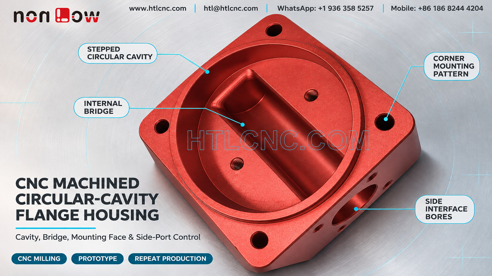
A CNC machined circular-cavity flange housing combines a square mounting face, stepped round recess, internal bridge, threaded face holes and side interfaces that require coordinated multi-face datums.
A CNC machined circular-cavity flange housing combines a square mounting flange with four corner holes, a stepped round recess, a raised internal bridge, threaded face holes and several side-interface openings. The photograph supports those visible geometric facts and a colored surface appearance, but it does not identify the material, finish process, tolerances, pressure capability or final machine. HTL CNC supports overseas OEMs, equipment builders, product-development teams and procurement organizations with drawing-based custom CNC machining from prototype qualification through repeat production.
Define the Housing Interfaces before Supplier Comparison
The RFQ should explain what seats on the square flange, what occupies the circular cavity, how the internal bridge interacts with the assembly and which side openings connect to mating parts. A simplified mating envelope can communicate fit, tool access and keep-out zones without revealing unrelated system details.
Provide the released 2D drawing and STEP model, exact material and condition, prototype and production quantities, annual demand, tolerances, finish, inspection-document scope, packaging and destination. HTL's custom CNC machining service reviews those inputs before selecting stock, setups, cutters and inspection methods.
Build the Datum Scheme from the Mounting Face
The broad square face and four corner holes are natural candidates for assembly control, but the released drawing must identify the functional datum. If the face seats against another component, its flatness and relationship to the circular cavity may influence sealing, alignment or clearance. None of those functions should be inferred from appearance.
A secondary datum may come from the cavity axis, one corner hole or a defined side surface. The datum sequence should prevent the side ports and internal bridge from being located independently in different setups. Supplier qualification should include a review of how each setup returns to that common coordinate system.
Machine the Stepped Circular Cavity as a Related Stack
The visible recess includes more than one diameter or level. The drawing should define each diameter, floor depth, shoulder width, corner radius, edge break and surface requirement. If a seat, seal or rotating element is involved, the customer must provide the corresponding interface and acceptance criteria.
Circular interpolation, boring or another qualified milling method may be used according to diameter, depth, material and tolerance. Inspection should verify the complete stack from the mounting datum rather than measuring each level from an uncontrolled local surface.
Control the Internal Bridge without Hiding the Cavity Floor
A raised transverse bridge divides part of the round recess. Its exact role is unknown, but its height, width, contour and position can affect tool access and assembly clearance. The 3D model should define the bridge junctions, while the drawing identifies any critical top face, sidewall or minimum section.
Roughing around the bridge requires chip evacuation and stable tool engagement. Long tools can deflect near the cavity floor, and aggressive deburring can soften bridge edges or change local clearance. The process plan should reserve appropriate finishing passes and confirm that inspection probes or optical methods can reach the controlled surfaces.
Coordinate Threaded Face Holes with the Cavity Axis
Two visible face holes appear threaded, but the image cannot establish their thread standard, pitch, class, depth or purpose. The purchase drawing should provide the complete callout, entry chamfer, usable engagement, bottom clearance and positional relationship to the mounting datum and cavity axis.
Thread gauges confirm size limits but not hole position or perpendicularity. A first-article plan may combine plug gauging with CMM or optical position checks. If coating is specified, masking or post-finish gauging requirements should be defined before production.
Treat the Corner Mounting Holes as One Pattern
The square flange has four corner openings. The drawing should define diameter, any counterbore or chamfer, true position, edge distance and whether one hole establishes orientation. Hole coordinates should be measured from the released datum system rather than only from neighboring holes.
Prototype assembly should use the intended fastener or an approved master plate. This reveals cumulative error between the square face, cavity and hole pattern. For repeat orders, a functional checking plate may supplement dimensional results when the buyer approves its design and calibration method.
Relate Side-Interface Bores to Internal Features
Several openings are visible on the side wall, including one larger feature and smaller surrounding holes. The photograph does not prove that they are ports, threads or connected passages. The section drawing and STEP model must define their diameters, depths, thread details, axes, internal intersections and required edge conditions.
Where side features intersect the circular cavity, burrs and trapped chips require special attention. Borescope inspection, controlled flushing, air-flow verification or another customer-approved method may be appropriate depending on cleanliness and function. HTL's multi-axis CNC machining service can be considered when fewer datum transfers materially improve access and positional control.
Plan Workholding around the Finished Colored Surface
The component presents a broad face, a deep recess and machined side walls. Workholding should support the body without marking customer-defined cosmetic zones or distorting the mounting face. Soft jaws, qualified nests or sacrificial surfaces may be evaluated from the real model and stock form.
If the visible color is applied before a secondary operation, finished areas must be protected. If it is applied after machining, coating allowance, masking and rack-contact locations should be defined. The photograph alone cannot establish whether the surface is anodized, plated, painted or produced by another process.
Build First-Article Inspection around Multi-Face Relationships
A useful first-article report can cover the mounting-face datum, overall envelope, corner-hole pattern, stepped cavity diameters and depths, bridge height and contour, threaded face-hole positions, side-interface axes, edge condition and drawing-defined geometric tolerances. It should record revision, fixture, measurement equipment and finish condition.
A related article on multi-port manifold cavity blocks discusses another component where side interfaces and internal cavities must share a controlled datum. This housing still requires its own part-specific plan based on its released drawings.
Validate the Prototype with the Mating Assembly
Prototype review should seat the housing on its mounting face, engage all four corner holes, place the intended component or approved envelope in the circular cavity, confirm clearance around the bridge and connect the side interfaces. If leakage, pressure, torque, motion or load testing is required, the customer must define the fixture, medium, cycle and pass criteria.
HTL's prototype and low-volume CNC machining service supports engineering samples and pilot quantities. Approved changes should update the 2D drawing, STEP model, finish notes and inspection plan under one controlled revision before low-volume ramp-up.
Transfer the Approved Housing into Repeat Production
Repeat-order consistency depends on controlled material, blank preparation, program revision, fixture identity, cutter-life limits, thread gauges, cavity inspection, cleaning records and formal change management. Sharing annual demand and release quantities helps plan material, machine capacity, inspection resources and delivery cadence.
Export packaging should protect the colored finish, mounting face, corner edges, cavity rim, threads and side openings. Nonabrasive separators, formed trays and suitable plugs may be selected according to the approved finish and cleanliness requirement. Labels should connect part number, revision, quantity and lot to inspection records.
RFQ Checklist for a Circular-Cavity Flange Housing
Send the released 2D drawing and STEP file, simplified mating envelope, exact material and condition, mounting-face datum, stepped cavity definition, bridge geometry, corner-hole pattern, threaded face-hole callouts, side-interface sections, tolerances, finish and masking notes, prototype and production quantities, annual demand, inspection documents, cleaning, packaging, destination and delivery target. Confidential files can be handled under the buyer's required document-control process.
This package allows HTL CNC to quote the CNC machined circular-cavity flange housing as a controlled multi-face manufacturing and inspection program rather than estimating material, finish or function from a photograph. For engineering review and quotation, visit www.htlcnc.com, email htl@htlcnc.com, send WhatsApp to +1 936 358 5257, or call mobile +86 186 8244 4204.
Have a part ready for engineering review?
Send your drawing, STEP file, material and quantity directly to HTL CNC for a manufacturing quotation.