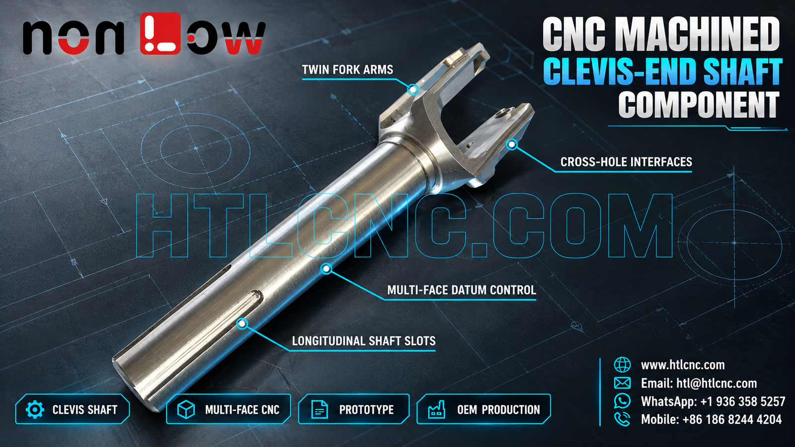
A CNC machined clevis-end shaft component combines a long cylindrical body, twin fork arms, cross-hole interfaces and longitudinal shaft slots that must remain coordinated around functional assembly datums.
A CNC machined clevis-end shaft component brings rotational shaft geometry and milled fork geometry into one part. The selected source image visibly shows a long cylindrical body, two parallel fork arms, elongated pockets in the arms, circular cross-hole interfaces and longitudinal slots along the shaft. It does not establish material grade, heat treatment, coating, exact tolerances, load rating or final application. HTL CNC supports drawing-based custom components for overseas OEMs, R&D companies, equipment builders, engineers and procurement teams from prototype review through repeat production.
Why Clevis-End Shaft Geometry Needs Coordinated Control
The shaft body, fork gap, arm thickness, cross-hole locations and longitudinal slots are not independent features when the component enters an assembly. A diameter may meet size while the fork is clocked incorrectly; both holes may accept a gauge pin while their common axis is displaced from the shaft centerline. The released drawing should therefore define the relationships that drive fit and motion.
A complete RFQ should include the controlled 2D drawing, STEP model, mating pin or simplified interface model, exact material and condition, prototype and production quantities, annual demand, critical tolerances, finish, inspection-document scope, packaging, destination and delivery target. HTL's custom CNC machining service reviews these inputs before fixture and inspection planning.
Establish the Shaft Axis and Functional Shoulder as Datums
The long cylindrical body provides a natural axis, but the drawing authority must identify the actual functional datum structure. If an assembly seats against the shoulder near the fork, that face may control axial location while the shaft diameter establishes the primary axis and a slot or another feature fixes rotation.
Using functional datums helps relate the fork opening, cross-holes and shaft slots to how the part is installed. It also prevents rough stock, a nonfunctional cosmetic surface or a convenient fixture contact from becoming an undocumented production reference. Datum targets and restrained conditions should be stated when a complete surface cannot be used reliably.
Control the Twin Fork Arms as One Clevis Interface
The two arms should be evaluated as a pair. Important drawing characteristics may include fork gap, individual arm thickness, parallelism, symmetry about the shaft axis, end profile and the position of the internal transition. The photograph shows elongated pockets within the arms, but their purpose is not proven and should not be inferred.
Machining strategy should account for the reduced stiffness that develops as the fork is opened and the arm pockets are milled. Balanced material removal, supported workholding and an appropriate finishing sequence can reduce clamp-driven movement. The drawing should state whether the fork gap and arm relationships are inspected free-state or under an approved restraint.
Treat the Cross-Holes as a Shared Pin Interface
Circular holes are visible at the fork ends. When a pin passes through both arms, individual hole diameter alone does not prove assembly. The hole axes may need to be coaxial, perpendicular to the relevant datum plane and correctly positioned from the seating shoulder and shaft axis.
Depending on tolerance and quantity, manufacturing may use drilling, boring, reaming or another qualified method after the arm geometry is stabilized. Inspection can combine calibrated plug gauges, CMM measurement and a customer-approved functional pin. Gauge fit should not replace positional evidence when the drawing requires both size and location control.
Define Longitudinal Shaft Slots Without Guessing Their Function
The image clearly shows long slots on the cylindrical body. Appearance does not establish whether they are keyways, clearance slots, drive features or passages. The product definition should specify slot width, depth, length, end geometry, surface condition, angular clocking and relationship to the fork and cross-hole axis.
A slot cut on a round surface also needs an unambiguous measurement method. Its depth may be defined from the shaft outside diameter, the shaft axis or a local chord according to the design. If two or more slots share an angular pattern, the drawing should control that pattern rather than relying on separate shop dimensions.
Plan Multi-Face CNC Machining Around Datum Transfer
The component combines turned or cylindrical surfaces with milled fork arms, arm pockets, end holes and shaft slots. A qualified route may use CNC turning followed by indexed milling, turn-mill equipment, controlled 3-axis refixturing, 5-axis CNC machining or another process selected from the real tolerance network.
The objective is to minimize uncertain transfers while maintaining tool access and part stability. If a secondary setup is required, the transfer surfaces and clocking method should be qualified in the first-article plan. Dedicated nests may improve repeatability for recurring orders, while prototype workholding may prioritize fast engineering changes.
Protect the Fork-to-Shaft Transition
The transition from the cylindrical body into the open clevis carries several intersecting surfaces. The photograph reveals a curved internal region, but not its complete radius or stress requirement. The drawing should define fillets, undercuts, blend geometry and any surfaces where tool marks or abrupt transitions are restricted.
Tool diameter and holder clearance should be checked against the full 3D model. A larger tool may improve stiffness but leave an unacceptable internal radius; excessive reach can reduce finish quality and positional consistency. Manufacturing feedback should be resolved in the controlled design files before production.
Separate Material, Heat Treatment and Finish Requirements
The photographed component has a bright metallic appearance. That does not identify alloy, temper, hardness, plating, passivation or other treatment. Purchase documents should state material specification, condition, approved alternates, certification needs, heat treatment, coating or finish, masking and post-process dimensional requirements.
Heat treatment and finishing can alter dimensions or surface condition at the shaft, fork gap, holes and slots. The routing should identify which critical features are finished or verified after each process. If corrosion resistance, wear or fatigue performance matters, the buyer should define the applicable standard and test method rather than relying on appearance.
Build Inspection Around Feature Relationships
A risk-based first-article report may cover shaft diameter and straightness, shoulder location, fork gap, arm thickness, arm parallelism, cross-hole size and common-axis position, shaft-slot dimensions and angular clocking, the fork-to-shaft transition and all drawing-defined geometric tolerances. The report should identify revision, datum setup, equipment and free or restrained condition.
Measurement may combine micrometers, height systems, plug and pin gauges, bore gauges, CMM probing and approved functional masters. HTL can align the inspection plan with buyer requirements for dimensional reports, material certificates, finish records or lot-level sampling.
Validate a Prototype with the Actual Mating Parts
A prototype should be tested with the intended mating pin, bearing or linkage interface, shaft receiver and any feature that engages the longitudinal slots. Engineering teams can then verify fork clearance, pin insertion, shoulder seating, rotational orientation, fastener access and free movement under real assembly conditions.
Performance under load, fatigue, impact, environmental exposure or lubrication requires customer-defined testing and acceptance criteria; it cannot be inferred from the source image. HTL's prototype and low-volume CNC machining service supports engineering samples and pilot lots before dedicated fixtures and sampling plans are locked.
Transfer the Approved Sample into Repeat OEM Supply
After validation, repeat production should control the approved material source, CNC program revision, fixture identity, transfer-datum method, tool-life rules, first-piece approval and inspection frequency. Changes to the fork, hole or slot process should trigger the requalification defined by the buyer's quality plan.
Packaging should prevent metal-to-metal contact and protect the fork tips, cross-hole edges, shaft surface and slots. Individual sleeves, pin protectors, formed trays or separators may be chosen according to finish and shipping route. Labels should identify part number, revision, quantity and lot for traceable receiving.
RFQ Checklist for a Clevis-End Shaft Component
Send the released 2D drawing and STEP file, mating-component models, exact material and condition, prototype and repeat quantities, annual demand, functional datum structure, shaft and shoulder requirements, fork gap and arm geometry, cross-hole definition, longitudinal-slot dimensions and clocking, transition radii, geometric controls, heat treatment, finish, inspection-document scope, packaging, destination and target schedule. Confidential technical files can be reviewed under the buyer's required document-control process.
This package allows HTL CNC to quote the CNC machined clevis-end shaft component as a coordinated machining, trial-fit and inspection program instead of estimating from a photograph. For another multi-interface linkage topic, see our guide to CNC machined split-clamp link arm control.
Website: www.htlcnc.com Email: htl@htlcnc.com WhatsApp: +1 936 358 5257 Mobile: +86 186 8244 4204
Have a part ready for engineering review?
Send your drawing, STEP file, material and quantity directly to HTL CNC for a manufacturing quotation.