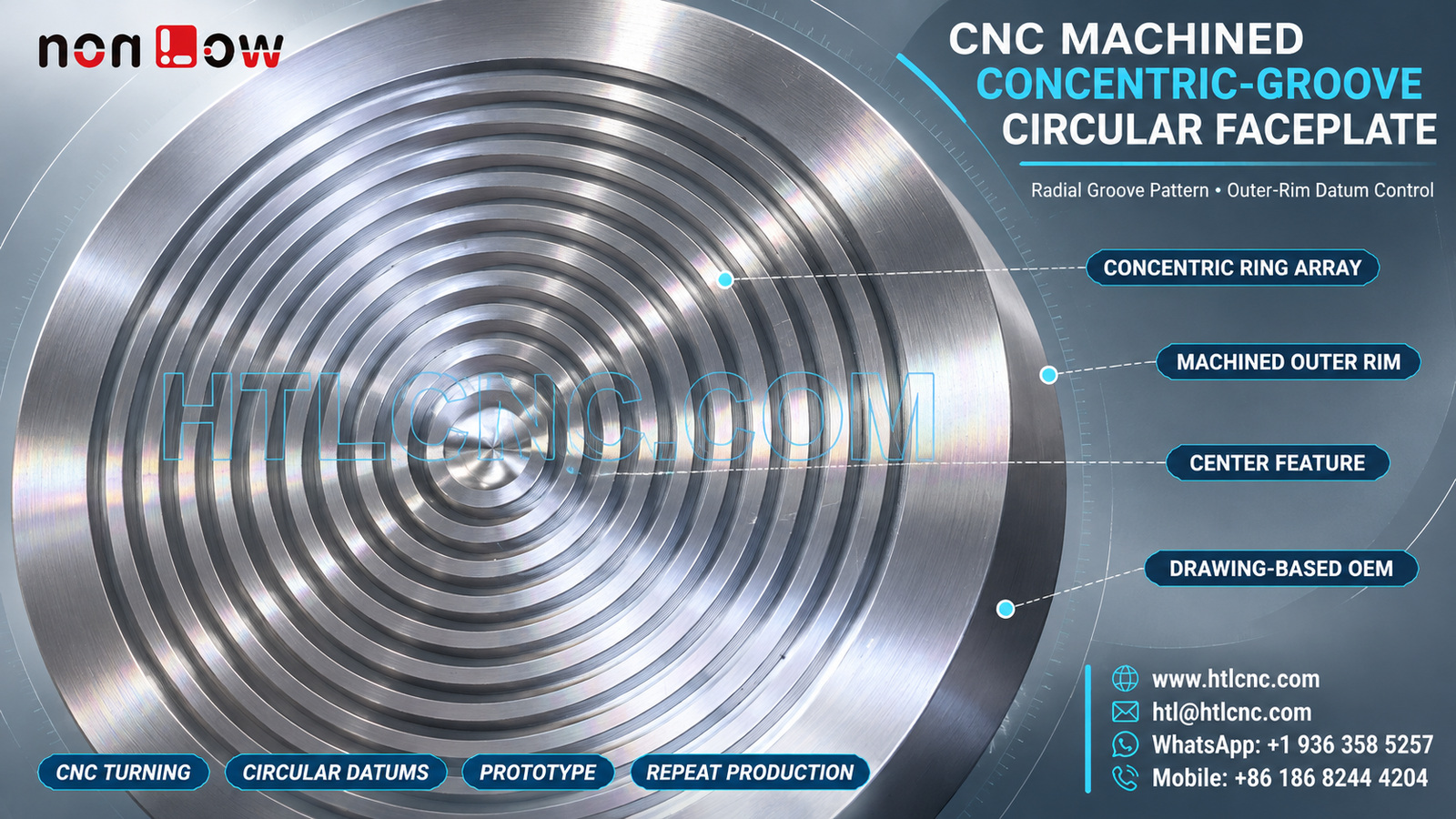
A CNC machined concentric-groove circular faceplate combines a repeated radial ring pattern, broad outer rim and center feature that require one controlled turning and inspection datum.
A CNC machined concentric-groove circular faceplate combines a broad circular body, a repeated radial ring pattern, a center feature and a defined outer rim. The photograph supports those visible geometric facts but does not establish the material, groove function, finish, tolerances or final equipment. HTL CNC provides drawing-based custom CNC machining for overseas OEMs, equipment builders, product-development teams, engineers and procurement groups from prototype qualification through repeat production.
Qualify the Part by Its Mating Surfaces
The RFQ should identify what locates on the outer diameter, whether either face seats against another component, what the center feature engages and whether the concentric pattern is functional or cosmetic. A simplified mating envelope helps the supplier understand clearance and datum intent without exposing unrelated system details.
Send the released 2D drawing and STEP model, exact material and condition, prototype and production quantities, annual demand, tolerances, finish, inspection documents, packaging and destination. HTL's custom CNC machining service reviews those inputs before selecting stock, workholding and measurement methods.
Establish One Axis for the Complete Ring Pattern
Every visible groove is concentric with the part center. The drawing should define the controlling axis and state whether it comes from the outside diameter, an internal fit, the center feature or another functional surface. Programming or measuring each ring from a convenient local edge can hide accumulated runout.
A qualified turning setup can relate the outer rim, groove diameters and center feature to one spindle axis. If refixturing is required, the process plan should explain how that axis is recovered and how runout is verified after the part is reversed.
Define Each Groove beyond Appearance
The engineering drawing should specify groove diameters or pitch, width, depth, root radius, flank angle where relevant, start and end boundaries, surface requirement and permitted edge treatment. A photograph cannot reveal whether the rings are sealing lands, grip features, thermal details or simply a visual pattern.
Tool geometry and insert condition influence width, floor form and surface texture. In-process checks should detect drift before multiple adjacent rings move outside the released requirement. Deburring must remove sharp edges without rounding functional lands or changing groove spacing.
Control the Outer Rim as a Functional Datum
The broad outside rim may locate the part, provide a contact face or serve only as an exterior boundary. The buyer should state diameter, thickness, flatness, parallelism, edge break and surface requirements according to its actual function.
If the rim is used for chucking during later operations, the supplier should protect finished surfaces and avoid distortion. Soft jaws, dedicated nests or sacrificial stock may be considered according to size, quantity and tolerance. Acceptance must remain based on measured part results rather than fixture choice alone.
Relate the Center Feature to the Circular Axis
The center area appears stepped, but the photograph does not prove a bore, boss, thread or mating function. Provide the complete section view and callouts for diameter, depth, profile, thread if present, runout and relationship to the groove pattern.
A center feature can meet its own local size while remaining eccentric to the outer rim. First-article inspection should therefore report coaxiality, runout or position using the drawing-defined datum structure. A customer-approved mating part can supplement dimensional evidence during prototype validation.
Select the Process Route from Geometry and Quantity
CNC turning is a natural candidate for circular features, but the final route depends on stock form, face access, groove profile, secondary holes or cutouts, finish and order quantity. Additional milling or multi-axis operations should be used only when the controlled design requires them.
HTL's CNC turning capability supports drawing-based circular components, while prototype and low-volume CNC machining allows engineers to validate fit and appearance before repeat orders. Supplier qualification should compare datum control, inspection access and repeatability rather than machine labels alone.
Separate Material and Finish Decisions
The bright metallic appearance does not confirm an alloy or treatment. State the exact material specification and condition, heat-treatment requirements where applicable, finish standard, cosmetic zones, masking, coating allowance and certificate scope. If the groove pattern must remain conductive or dimensionally unchanged, identify the surfaces that require protection.
An approved appearance sample can define color and texture, but it should supplement written criteria. Drawings should state whether critical dimensions apply before or after finishing and how handling marks, rack points or local color variation are evaluated.
Build First-Article Inspection around Circular Relationships
A useful first-article report can include outer diameter and rim thickness, face flatness, overall thickness, groove diameters, widths and depths, ring-to-ring spacing, center-feature geometry, runout and drawing-defined geometric tolerances. Measurement may combine calibrated diameter tools, depth measurement, profile inspection, roundness equipment or CMM methods according to the released limits.
The report should identify drawing revision, datum setup, measurement equipment and finish condition. Sampling of repeated grooves is acceptable only when the customer approves the locations and frequency.
Validate the Prototype before Repeat Supply
Prototype review should confirm seating, radial clearance, center engagement, axial stack and the customer's functional test. If the ring pattern has acoustic, thermal, sealing, optical or another special purpose, the buyer must define the test fixture and pass criteria; appearance alone is insufficient.
After approval, controlled material, CNC program revision, jaw or fixture identity, tool-life limits, first-piece inspection, deburring standards and formal change management support repeat-order consistency. Annual demand and release cadence help plan stock, machine capacity, inspection and delivery.
Protect Circular Features during Export Packaging
Packaging should keep finished faces, ring edges, the outer rim and center feature from contacting adjacent parts. Nonabrasive separators, formed trays and suitable surface protection may be selected from the approved finish and shipment route. Labels should connect part number, revision, quantity and lot to inspection records.
RFQ Checklist for a Concentric-Groove Circular Faceplate
Provide the released 2D drawing and STEP file, mating interfaces, exact material, functional axis, complete groove schedule, outer-rim requirements, center-feature definition, tolerances, finish and masking notes, prototype and production quantities, annual demand, inspection documents, packaging, destination and delivery target. Confidential drawings can follow the buyer's required document-control process.
This package allows HTL CNC to quote the CNC machined concentric-groove circular faceplate as a controlled turning, inspection and supply program rather than guessing material or function from a photograph. For engineering review and quotation, visit www.htlcnc.com, email htl@htlcnc.com, send WhatsApp to +1 936 358 5257, or call mobile +86 186 8244 4204.
Have a part ready for engineering review?
Send your drawing, STEP file, material and quantity directly to HTL CNC for a manufacturing quotation.