CNC machined control panel variant production coordinates shared panel geometry, display and key openings, finish approvals, revision control and repeat OEM supply.
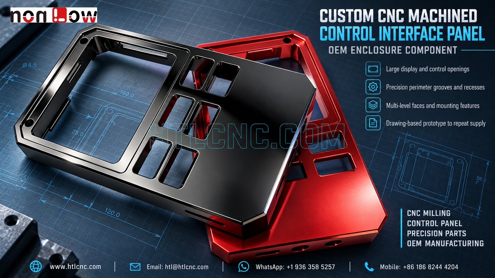
CNC machined control panel variant production is needed when an OEM product family uses related interface panels in different configurations or visual finishes. The photograph shows one black and one red machined panel with a large rectangular window, six smaller rectangular openings, perimeter recesses, corner mounting holes, side slots and multi-level outer profiles. These visible parts support a useful sourcing question: how can a supplier control common geometry while preventing color, revision and configuration mix-ups across recurring orders? HTL CNC provides custom CNC machining, precision CNC parts, prototype validation, low-volume production and repeat drawing-based manufacturing for overseas equipment builders, product-development companies, contract manufacturers, engineers and procurement teams. The image does not establish material grade, finish process, tolerance, final application or whether both panels share an identical drawing; those facts must come from controlled customer documentation.
Why Product Variants Need More Than One Approved Drawing
Related panels may share an outside profile while changing an opening pattern, engraving, surface treatment or assembly destination. A buyer should therefore define each sellable or buildable configuration with its own part number, revision and finish code. A color description in an email is not a reliable substitute for a released specification.
The quotation package should include a configuration matrix showing which 2D drawing, STEP model, surface specification, cosmetic standard, label requirement and packaging instruction belongs to each variant. This prevents the supplier from applying one version's finish or opening layout to another version's hardware.
Common Geometry and Controlled Differences
The visible black foreground panel includes a large window, six smaller rectangular openings and a stepped perimeter. A related red panel is positioned behind it. Where an OEM intentionally reuses common geometry, a family-level engineering review can identify which datums, tools, fixtures and inspection methods may be shared. The released files must still identify every difference explicitly.
Shared workholding can improve repeatability and reduce setup effort only when the locating scheme remains valid for each revision. If a new opening breaks into a fixture contact, changes stiffness or requires different cutter access, the manufacturing plan must be requalified rather than copied automatically.
Precision CNC Panel Machining Around Rectangular Openings
Display and key openings are not controlled only by length and width. Internal corner radius, edge break, wall condition, position from the panel datums and relationship to the perimeter recess may affect the fit of mating components. End-mill diameter and tool reach should be reviewed against the specified corner geometry.
Closely spaced openings leave narrow webs between them. Roughing and finishing should control cutting load so these regions remain stable. Deburring must remove loose edges without enlarging an opening, rounding a locating shoulder or damaging a cosmetic face. Any requirement for a near-sharp internal corner should be stated in the drawing because ordinary CNC milling produces a tool-radius condition.
Perimeter Recesses, Mounting Holes and Multi-Level Faces
The broad outer frame contains a recessed perimeter path and mounting holes near the corners. These features may locate a display, cover, gasket or another customer-defined assembly, but their function cannot be inferred from the image. The drawing should identify the primary seating face and define depth, profile and hole position from a stable datum system.
Side slots and different face levels may require controlled refixturing or indexed access. The suitable route can use 3-axis machining, 4-axis positioning or 5-axis CNC machining according to actual access, tolerance, rigidity and quantity. Machine-axis count is a process choice, not a substitute for datum planning.
Finish Approval for Black and Red Panel Versions
The photograph shows different colors, but it does not prove anodizing, paint, plating or any other specific treatment. The OEM should release the material and finish standard, approved color reference, gloss or texture range, masking requirements, coating allowance and cosmetic acceptance zones. A physical limit sample can be useful when visual consistency matters.
Functional openings, threads, close-fit surfaces and perimeter recesses may need masking or post-finish inspection. Finish-lot identity should remain connected to the part number and revision. When two variants are packed in the same shipment, clear labeling and physical separation reduce the risk of a receiving or assembly mix-up.
Inspection Evidence for Variant Control
A risk-based inspection plan may cover outer profile, window size and position, small-opening pattern, perimeter-recess depth, corner-hole location, side-slot geometry, face levels and drawing-defined geometric controls. Measurement can combine calibrated hand tools, depth measurement, pin gauges, optical inspection, height systems and CMM methods according to feature access and tolerance.
For supplier qualification, buyers should specify whether prototypes require selected dimensional results, a first-article inspection report, finish approval records or assembly evidence. Repeat production can use a defined sampling plan and lot records. Every report should identify the exact part number, revision, configuration and finish code so acceptable data from one variant is not incorrectly applied to another.
Prototype Builds and Engineering Change Control
A prototype should be checked with the intended display, keys, switches, fasteners or mating structure where applicable. The engineering team can verify opening clearance, perimeter seating, fastener access, edge condition and the selected finish standard. If testing leads to a geometry change, the new model and drawing should be released together.
After sample approval, controlled CNC programs, qualified fixtures, approved finish sources, first-piece checks and formal change management support low-volume ramp-up and repeat orders. HTL's prototype and low-volume CNC machining service supports staged validation, while its custom CNC machining capability supports documented repeat supply.
Packaging and Delivery Planning for Product Families
Broad cosmetic panels can be damaged by metal-to-metal contact. Protective film, individual sleeves, separators or formed trays may be selected from the actual finish and geometry. Labels should show part number, revision, configuration, quantity and production lot. Mixed-variant cartons should use an agreed packing list and internal separation.
Annual demand, release frequency, destination and forecast flexibility help the supplier plan raw material, machining capacity, finish batches, inspection workload and export packaging. Procurement teams should also define how obsolete revisions are quarantined when an engineering change becomes effective.
RFQ Checklist for CNC Machined Control Panel Variants
Send the released 2D drawings and STEP files for every required version. Include the configuration matrix, specified material, prototype and production quantities, annual demand, functional datums, opening and recess tolerances, finish and color requirements, cosmetic zones, inspection-document scope, packaging, destination and delivery schedule. HTL CNC can then review the CNC machined control panel variant production project and prepare a controlled manufacturing, quality and supply plan.
Website: www.htlcnc.com Email: htl@htlcnc.com WhatsApp: +1 936 358 5257 Mobile: +86 186 8244 4204
Have a part ready for engineering review?
Send your drawing, STEP file, material and quantity directly to HTL CNC for a manufacturing quotation.