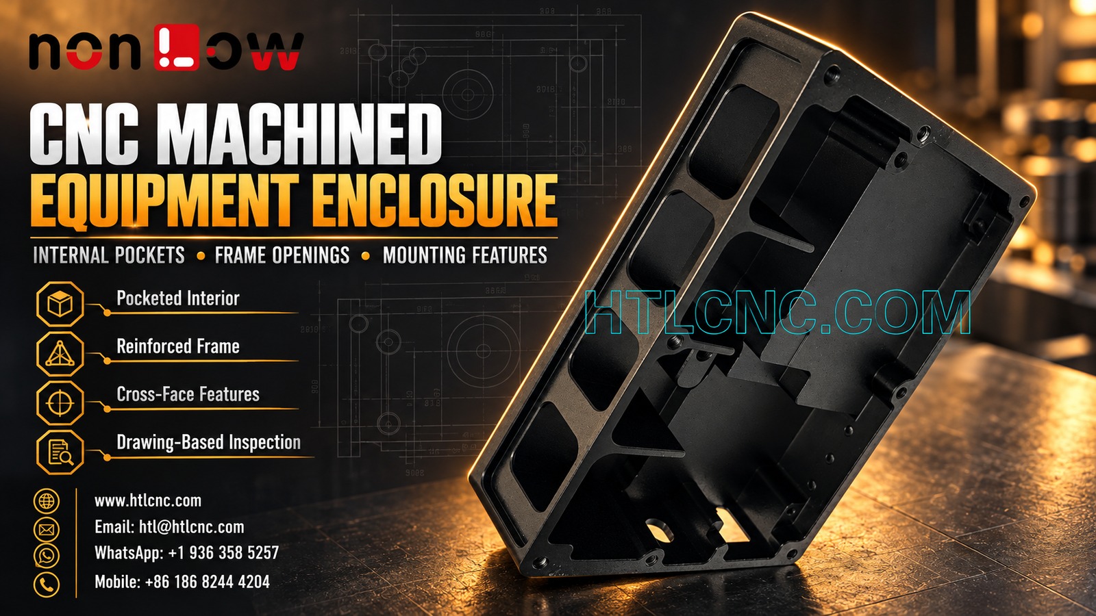
A CNC machined equipment enclosure combines a deep pocketed interior, repeated frame openings, perimeter mounting features and cross-face interfaces that must remain coordinated through machining, finishing and inspection.
A CNC machined equipment enclosure is more than a box with material removed. The selected photograph visibly shows one long rectangular black-finished enclosure with a deep internal cavity, repeated rectangular openings along one frame rail, internal ribs, perimeter holes and several cross-face features. These observations support an enclosure-machining topic, but the image does not prove material, coating chemistry, sealing level, electronics, load, thermal duty, tolerance or final application. HTL CNC supplies drawing-based custom enclosure machining for overseas OEMs, product-development companies, equipment builders, engineers and procurement teams from prototype review through repeat production.
What Should an RFQ Include for a CNC Machined Equipment Enclosure?
Send the released 2D drawing and STEP file, exact material and condition, prototype and production quantities, annual demand, functional datums, critical interfaces, finish specification, inspection-document scope, packaging requirements, delivery destination and target schedule. Mark every surface that locates a board, cover, connector, seal, bracket or neighboring component.
The supplier also needs the mating-part models where fit depends on a complete stack. A photograph cannot establish whether an opening is cosmetic, structural or functional. If ingress protection, thermal performance, electrical grounding, pressure, impact or vibration matters, provide the customer-approved test standard, fixture and acceptance criteria.
Establish a Datum Structure Before Pocket Machining
The visible enclosure combines an outside frame, a broad internal floor and multiple perimeter interfaces. The drawing should identify the primary mounting plane, one longitudinal reference and one clocking feature. Hole positions, pocket depths, frame openings and cover interfaces can then reference the same stable coordinate system.
Starting every feature from a convenient raw edge can accumulate error across a long housing. A defined datum scheme also makes setup transfer and CMM reporting easier to compare. HTL's custom CNC machining service reviews datum selection, stock condition, setup count, tool access and inspection strategy before the production route is fixed.
Rough Deep Internal Pockets Without Distorting the Frame
Large cavities remove a high percentage of the starting blank and can release residual stress. Thin rails and isolated ribs may move as surrounding stock disappears. A stable process may use balanced roughing, controlled stock allowance, rest periods when appropriate and final finishing after the part reaches a predictable condition.
Minimum wall, floor thickness, inside corner radii, draft-free transitions and cutter reach should be reviewed directly from the model. The buyer should avoid specifying unnecessarily small internal radii where a larger cutter could improve stiffness, cycle time and surface consistency. Exact allowances depend on material, blank route, tolerance and quantity rather than appearance.
Treat the Repeated Frame Openings as a Controlled Pattern
One long rail visibly contains several rounded rectangular openings separated by narrow webs. The released drawing should define each opening profile, corner radius, spacing, remaining web width, edge condition and position from functional datums. Pattern pitch alone is not enough if one end opening or local transition differs.
Machining sequence should protect the slender bridges between openings. Tool entry, support and deburring methods need to avoid bending or rolling those edges. Optical measurement or CMM profile inspection can verify the complete pattern when simple calipers cannot establish its relationship to the enclosure frame.
Coordinate Perimeter Holes and Cross-Face Features
The photograph shows holes and machined details distributed around more than one face. Their functions are unknown, so the drawing must state hole size, thread callout where applicable, depth, counterbore or countersink, positional tolerance, edge distance and datum reference. Blind threads also need usable engagement depth rather than drill depth alone.
Cross-hole and side-feature alignment can be lost when each face is programmed as an independent setup. Indexed workholding, qualified soft jaws, a fixture nest or multi-axis machining may reduce transfers, but machine choice should follow tolerance, access and volume. First-article records should report the relationships that matter to assembly, not only individual diameters.
Define Cover, Seal and Internal-Mounting Interfaces Explicitly
A perimeter recess or narrow ledge can serve many purposes, but no sealing function should be inferred from the image. If a cover, gasket or O-ring is involved, specify the mating geometry, groove standard, surface-finish requirement, corner details, allowable interruptions, compression target and leak or ingress test.
Internal platforms, bosses or ribs may locate a board, sensor, bracket or another assembly. Provide mating-part data, screw access, tool clearance, stand-off heights and any keep-out zones. These inputs let the machining supplier protect the true interfaces while applying practical tolerances elsewhere.
Manage Flatness After Heavy Material Removal
A long enclosure can meet local pocket dimensions yet fail at a broad mounting face or cover plane. The drawing should distinguish overall flatness, local flatness, parallelism and profile requirements. Measurement should occur in the defined free or restrained state and at the specified finish condition.
Fixture pressure can temporarily flatten a flexible frame, so final inspection after unclamping is important unless the customer specifies a functional restraint. Depending on size and tolerance, inspection may use a surface plate and height system, CMM, optical equipment or a customer-approved functional fixture.
Specify the Black Finish Without Guessing the Process
The dark appearance does not establish substrate, anodizing, conversion coating, paint or another treatment. The RFQ should state the exact finish specification, color and gloss range, texture, thickness allowance, cosmetic zones, masking locations, electrical-contact areas, corrosion requirement and certificate scope.
Threaded holes, locating bores, seal lands and ground-contact areas may need masking or post-finish acceptance dimensions. The drawing should say whether dimensional limits apply before or after treatment. A controlled appearance sample can supplement, but not replace, written finish and cosmetic criteria.
Plan Deburring and Cleaning for Internal Corners
Pocket intersections, frame openings, threaded holes and cross-drilled features can retain burrs or chips. A generic deburr note may not protect seal lands, wire routes or narrow mounting faces. Identify the allowed edge break for functional and nonfunctional edges, and call out any edge that must remain sharp for a defined reason.
Cleaning requirements should cover chips, cutting fluid, abrasive residue and finishing contamination inside blind features. Where direct visual access is limited, borescope inspection, controlled flushing, particle-count requirements or another customer-approved method can be included.
Validate Prototype Assemblies Before Repeat Production
Prototype quantities allow the OEM team to check cover seating, gasket compression where applicable, board or bracket alignment, connector access, fastener engagement, cable clearance and neighboring-part fit. Environmental, thermal, vibration, impact or ingress tests require customer-defined equipment and pass criteria; they cannot be promised from the photograph.
HTL's prototype and low-volume CNC machining service supports engineering samples and pilot lots before dedicated fixtures and sampling plans are locked. Any approved change to the pocket, frame pattern, hole locations, material or finish should update the 2D drawing and STEP model under the same revision.
Transfer the Approved Enclosure into Repeat OEM Production
Repeat supply depends on controlled stock sources, fixture identification, CNC program revision, first-piece approval, tool-life rules, in-process checks and final inspection sampling. The datum path used for the accepted prototype should remain visible in setup instructions and reports.
Packaging should prevent finished frames and broad faces from rubbing against neighboring parts. Formed trays, nonabrasive separators, protective films or individual sleeves may be selected from the finish sensitivity and shipment route. Labels should identify part number, revision, quantity and lot traceability required at receiving.
RFQ Checklist for a CNC Machined Equipment Enclosure
Provide the released drawing and STEP model, mating cover and internal-component data, exact material, blank condition, prototype and production quantities, annual demand, functional datums, pocket and wall definitions, frame-opening pattern, complete hole schedule, cover or seal interface, finish and masking requirements, cosmetic standard, inspection report scope, cleaning, packaging, destination and delivery target. Confidential files can be reviewed under the buyer's required document-control process.
A complete package allows HTL CNC to quote the CNC machined equipment enclosure as a controlled milling, finishing and inspection program rather than guessing function from visible geometry. For a related multi-face housing topic, review our guide to multi-port manifold cavity-block machining.
Website: www.htlcnc.com Email: htl@htlcnc.com WhatsApp: +1 936 358 5257 Mobile: +86 186 8244 4204
Have a part ready for engineering review?
Send your drawing, STEP file, material and quantity directly to HTL CNC for a manufacturing quotation.