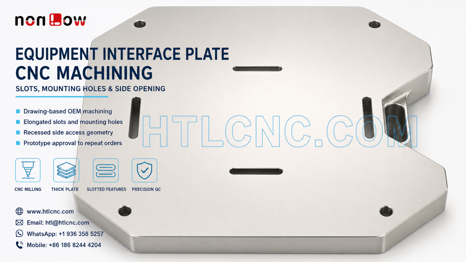
Drawing-based B2B CNC manufacturing for thick equipment interface plates with elongated alignment slots, mounting holes, profiled edges and a recessed side opening.
A thick equipment interface plate can combine a broad reference face, elongated slots, corner mounting holes, a profiled outer boundary and a recessed opening on an adjacent face. This geometry may look less complex than a deep enclosure, yet the relationship between the slots, mounting pattern, plate face and side feature can determine whether the component locates and assembles correctly. The visible part supports this general manufacturing discussion; its material, dimensions, tolerances and end use must be defined by the customer's released files.
HTL CNC provides drawing-based custom CNC machining for overseas OEMs, equipment builders, product-development companies, contract manufacturers, engineers and procurement teams. Manufacturing recommendations are based on the controlled 2D drawing, STEP model and approved sample. A photograph alone cannot establish material grade, tolerance, coating, certification or functional application.
Supplier Qualification for a Slotted Interface Component
A complete RFQ should include the released STEP file, controlled 2D drawing, specified material, prototype quantity, expected production quantity or annual demand, critical dimensions, surface-finish requirements, inspection-document scope, packaging expectations and delivery destination. The drawing should identify the primary datum face and state which holes, slots or side features are functionally related.
During supplier onboarding, buyers should also define confidentiality requirements, sample-approval criteria, revision ownership and the process for engineering changes. Programs, fixture instructions and inspection records should remain traceable to the approved part number and revision, especially when several product variants share a similar outer profile but use different slot or opening locations.
Elongated Slots as Controlled Alignment Features
Four elongated slots are visible on the main face. Depending on the assembly design, a slot may provide adjustment, clearance, location or access, but its exact function should not be inferred from appearance. The drawing should define slot width, length, end radii, position and any relationship to the mounting-hole pattern or outer profile.
Slot width and centerline position may require different process controls. Profile milling, suitable cutter engagement and a stable finishing pass can help establish the drawing-defined geometry. Deburring is important because rolled edges or residual burrs can interfere with fasteners, locating elements or mating hardware even when the measured slot width appears acceptable.
Mounting Holes and Outer-Profile Relationships
The corner holes and irregular outer boundary create an interface that must be inspected as a coordinated pattern rather than as unrelated dimensions. Hole diameter alone does not confirm assembly fit if the hole locations are shifted relative to the slots or reference face. The engineering review should identify which features establish location and which allow clearance.
The profiled perimeter includes chamfered corners and a local side recess. Cutting sequence and support should preserve edge condition while maintaining the reference face. If the plate is produced from thick stock, workholding should avoid forcing the component into a temporary condition that changes after release.
Recessed Side Opening and Multi-Face Access
The adjacent side contains a recessed rectangular opening with rounded internal corners. This feature introduces a second machining orientation and may require controlled reclamping, indexed positioning or multi-axis access according to the actual depth, datum relationship and cutter clearance. The route should be selected from the drawing and production volume rather than from a generic preference for a specific machine type.
Where the side opening must align with internal hardware or a feature on the main face, the relationship should be included in first-article inspection. Internal corner radii, wall thickness, opening depth and edge condition should be specified rather than left to visual interpretation.
Workholding and Surface Stability
A broad plate face can appear rigid, but removing material for slots, holes and the side recess changes local stiffness. Roughing and finishing order should retain stable support around the profiled boundary and avoid excessive clamping near interrupted features. The component should be checked in its free state when the drawing includes face, profile or positional requirements.
For prototype quantities, adaptable workholding may be practical while the design is still changing. After sample approval, documented fixture locations, support points, tool lists and loading instructions can improve consistency during low-volume ramp-up and recurring production.
Inspection of Slots, Pattern and Side Geometry
An agreed inspection plan may cover the reference face, plate thickness, slot width and length, slot centerlines, hole diameters, hole positions, outer profile, side-opening dimensions, edge condition and any drawing-specified geometric controls. Calipers, micrometers, height measurement, pin gauges, optical equipment and CMM inspection may be selected according to feature geometry and tolerance.
Overseas buyers should state whether prototypes or batch shipments require selected dimensional results, a first-article report, material or finishing documents and lot-level inspection records. Each report should identify the exact part number, revision and production batch so repeat orders remain auditable.
Surface Finish and Export Packaging
The component may be supplied as machined or with a customer-specified treatment compatible with the released material. Blasting, anodizing, plating, passivation, brushing, polishing, painting or another process should be considered only when defined in the RFQ. Cosmetic zones, masked faces, coating allowance, color requirements and protected interfaces should be documented before quotation.
Broad faces and finished edges can be vulnerable to scratches during handling and transport. Protective separation, sleeves, trays or other export packaging can reduce metal-to-metal contact. Packaging labels and batch identification should align with the customer's receiving and inventory process.
Prototype Approval and Repeat-Order Planning
Prototype validation should check slot adjustment range, mounting-hole alignment, mating-face contact, side-opening clearance, edge condition and any surface-finish assumptions. Procurement teams can also review engineering communication, document control, responsiveness, inspection evidence, packaging and delivery performance before approving repeat supply.
After the sample is accepted, controlled programs, stable workholding, defined inspection points and revision management support recurring orders. Forecasts or annual demand help plan material, machine capacity, fixture investment, finishing batches and delivery schedules.
RFQ Information for Engineering Review
Send the released 2D drawing and STEP file together with the specified material, prototype and production quantities, annual demand, critical slot and hole tolerances, surface finish, inspection-document requirements, packaging needs and delivery destination. HTL CNC can then review the functional datum relationships and prepare a realistic manufacturing proposal.
Website: www.htlcnc.com Email: htl@htlcnc.com WhatsApp: +1 936 358 5257 Mobile: +86 186 8244 4204
Have a part ready for engineering review?
Send your drawing, STEP file, material and quantity directly to HTL CNC for a manufacturing quotation.