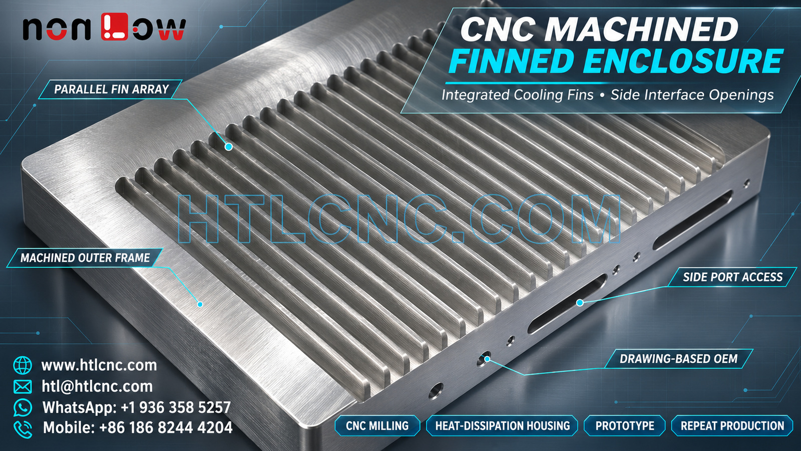
A CNC machined finned heat-dissipation enclosure combines a dense parallel fin array, broad perimeter frame and multiple side openings that must be coordinated from a stable drawing-defined datum system.
A CNC machined finned heat-dissipation enclosure combines a broad rectangular frame, a dense parallel fin array and several side-interface openings in one integrated body. Those visible features support a heat-dissipation housing category, but the photograph does not establish the alloy, thermal load, enclosure rating, finish, tolerances or final application. HTL CNC provides drawing-based custom CNC machining for overseas OEMs, product-development companies, equipment builders, engineers and procurement teams from prototype validation through repeat production.
Start the RFQ with Thermal and Assembly Interfaces
A supplier needs more than an exterior model to plan a finned housing. Identify the heat source, contact footprint, mating cover or internal component, mounting orientation, keep-out zones and the side openings that connect to the rest of the assembly. Thermal targets and environmental requirements must come from the customer; they cannot be inferred from fin appearance.
Send the released 2D drawing and STEP file, exact material and condition, prototype and annual quantities, critical tolerances, finish, inspection-document scope, packaging and destination. HTL's custom CNC machining service uses that package to review stock form, fixture access, cutter reach, deburring and measurement strategy before quotation.
Treat the Parallel Fin Array as a Controlled Machining Feature
The visible array contains many long, closely spaced fins. The drawing should define fin thickness, spacing, height, root radius, end condition and any permitted variation across the array. A generic overall width does not control individual fins or the channels between them.
Tool selection depends on channel width, depth, material, quantity and surface requirements. Stable engagement, chip evacuation and cutter-life monitoring are important because a damaged or deflected tool can affect several adjacent channels before the issue becomes obvious. The process plan should also state whether minor edge blending is allowed at fin tips and roots.
Protect Thin Features during Workholding
Clamping directly across the fin field can mark or distort thin features. A qualified fixture should locate from robust external faces, a rear surface or customer-defined mounting features while keeping force away from the cooling array. The actual datum sequence must follow the released drawing and assembly function.
Stock removal can also release residual stress and influence broad-face flatness. Roughing, controlled rest periods, part flipping or balanced finishing passes may be evaluated when part size, material and tolerance require them. These choices should be documented during prototype review rather than treated as universal rules.
Relate Side Openings to the Main Enclosure Datum
The photograph shows elongated side openings and several smaller holes. Their exact function, thread status and internal connection are not confirmed. The engineering package should define every opening's size, depth, corner radius, axis, thread callout where applicable, positional tolerance and relationship to the functional mounting datum.
Side features can meet local dimensions while drifting relative to an internal board, connector, cover or mating bracket. First-article inspection should therefore report their position from the same coordinate system used for the frame and fin array. A customer-approved mating fixture can supplement dimensional results when installation fit is important.
Coordinate the Outer Frame, Contact Face and Fin Field
The wide perimeter may provide stiffness, mounting area or a sealing boundary, but its function must be identified by the buyer. Define flatness, parallelism, surface texture, edge breaks, hole patterns and any protected contact zones. If a heat source contacts another face, specify its flatness and finish separately from cosmetic exterior surfaces.
The fin field should not be programmed as an isolated decorative feature. Its location, end margins and channel orientation should remain coordinated with the outer frame and side interfaces. A common datum strategy reduces accumulated error when the component is reoriented for multi-face machining.
Select the Machining Route from Access and Tolerance
A rectangular heat-dissipation housing may be produced through multiple qualified setups, indexed machining or another multi-axis route. Machine-axis count alone is not a quality claim; the practical route depends on the envelope, channel depth, side-feature direction, tolerance stack, quantity and inspection access.
HTL's 5-axis CNC machining capability can be reviewed when controlled reorientation or access from several directions would reduce datum transfers. Simpler geometry may be more efficient on another qualified process. The quotation review should compare risk, cycle time, fixture complexity and measurable results.
Separate Material and Finish Requirements
The light metallic appearance does not prove a specific alloy or surface treatment. State the exact material specification and condition, finish standard, color, cosmetic zones, masking locations, coating allowance and certificate requirements. If thermal contact or electrical continuity matters, identify the surfaces that must remain uncoated or receive a controlled post-finish condition.
Fin channels can be difficult to inspect visually after finishing. An approved sample and written acceptance criteria can define color, texture, rack marks and coverage, while dimensional requirements clarify whether measurements apply before or after treatment.
Build Inspection around Function, Not Only Overall Size
A first-article plan for a CNC machined finned heat-dissipation enclosure may include the outer envelope, functional mounting face, fin thickness and spacing, channel depth, frame width, side-opening size and position, hole patterns, edge condition and drawing-defined geometric tolerances. Measurement methods should be chosen before production so probes, optical systems or dedicated gauges can reach the required areas.
Inspection records should identify drawing revision, datum setup, equipment and finish condition. For closely spaced fins, sampling may be appropriate only when the customer approves the locations and frequency. Any thermal, ingress, vibration or assembly test requires a separately defined fixture and pass criterion.
Validate the Prototype in the Real Assembly
Prototype evaluation should confirm mounting-face contact, enclosure fit, connector or cable access through the side openings, cover clearance and the customer's thermal test under defined operating conditions. Dimensional acceptance does not replace thermal validation, and a thermal result does not replace geometric inspection.
HTL's prototype and low-volume CNC machining service supports engineering samples and pilot quantities before fixture details, inspection plans and finishing controls are locked. Approved changes should update the 2D drawing, STEP model and test requirements under one controlled revision.
Plan Repeat OEM Production and Export Handling
Repeat-order consistency depends on controlled material, fixture identity, CNC program revision, cutter-life rules, first-piece approval, channel cleaning, finish protection and formal change management. Annual demand and release cadence help the supplier plan raw material, machine capacity, inspection and delivery.
Packaging should prevent fin tips, broad contact faces and side openings from carrying impact or abrasion loads. Formed trays, nonabrasive separators and suitable protective caps may be selected from the approved finish and shipment route. Labels should connect part number, revision, quantity and lot to inspection records.
RFQ Checklist for a Finned Heat-Dissipation Enclosure
Provide the released 2D drawing and STEP model, exact material, thermal contact and mounting interfaces, fin geometry, side-opening schedule, hole and thread table, functional datums, tolerances, finish and masking notes, prototype and production quantities, annual demand, inspection documents, customer-defined thermal or environmental tests, packaging, destination and delivery target. Confidential files can follow the buyer's required document-control process.
This information allows HTL CNC to review the CNC machined finned heat-dissipation enclosure as a controlled machining, inspection and supply program instead of guessing function from a photograph. For engineering review and quotation, visit www.htlcnc.com, email htl@htlcnc.com, send WhatsApp to +1 936 358 5257, or call mobile +86 186 8244 4204.
Have a part ready for engineering review?
Send your drawing, STEP file, material and quantity directly to HTL CNC for a manufacturing quotation.