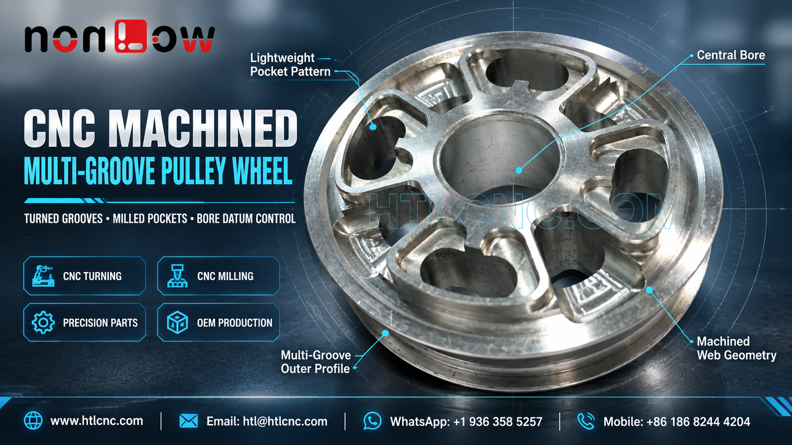
A CNC machined multi-groove pulley wheel combines a central bore, repeated lightweight pockets, a shaped web and multiple circumferential grooves that must stay related to one rotational datum.
A CNC machined multi-groove pulley wheel combines rotational and milled geometry in one compact circular component. The selected photograph visibly shows a central through-bore, several circumferential grooves around the outside diameter, repeated open pockets, a shaped web and blended pocket edges. The image does not establish the material grade, groove standard, operating speed, load, balance requirement, tolerances, finish or final application. Those requirements must come from the buyer's released 2D drawing, STEP model and assembly specification. HTL CNC supports overseas OEMs, equipment builders, product-development companies, engineers and procurement teams with drawing-based custom pulley machining, prototype validation, low-volume production and repeat supply.
Start with the Pulley Axis and Functional Faces
The central bore usually provides an important rotational reference, but the drawing must identify the actual primary datum, locating diameter, seating face and clocking feature. The outer groove profile, front and rear faces, pocket pattern and any hidden keyway or fastening detail should be related to that controlled axis rather than dimensioned independently from convenient raw edges.
A buyer should also provide the mating shaft, bearing, spacer or hub information that affects fit and axial location. HTL's CNC turning and turn-mill machining service reviews these relationships before selecting stock, jaw strategy and machining sequence.
Define Every Circumferential Groove from the Drawing
The visible outside diameter contains multiple parallel grooves, but a photograph cannot prove whether they guide a belt, retain another component or provide a different function. The released drawing should define groove count, pitch, width, depth, included angle or radius, root geometry, flank condition, runout and the datum used for inspection.
Where groove geometry is functional, a profile gauge, optical system or traceable contour measurement may be more useful than checking only width and depth with general-purpose tools. Burrs and rolled edges at the groove crests should be controlled without changing the specified profile.
Keep the Central Bore Concentric with the Outer Profile
Bore diameter alone does not confirm rotational performance. The buyer should state fit, roundness, cylindricity, surface finish, straightness and runout requirements where they matter. If the bore includes a hidden step, keyway, spline or retaining feature, the complete model and section views are needed for process and inspection planning.
Machining the critical bore, outside diameter and groove references in one qualified turning setup can reduce datum-transfer error when geometry and stock permit. If the part must be reversed, controlled soft jaws or a dedicated nest can locate an established surface while protecting finished groove crests.
Mill the Pocket Pattern Without Weakening the Web
The face contains repeated pockets separated by narrow web sections. Their shapes are not simple copies: local openings, corner blends and web transitions visibly vary around the circle. The drawing should therefore define the complete pocket profiles, remaining wall thickness, radii, angular locations and any intentionally asymmetric features.
Pocket roughing changes stiffness and can release residual stress. A stable route may establish the rotational geometry first, leave balanced stock around sensitive webs, rough the openings in a controlled sequence and finish the functional faces after the part has reached a predictable condition. The exact sequence depends on material, blank condition, tolerance and quantity.
Coordinate CNC Turning and CNC Milling
The concentric bore, outside diameter, end faces and outer grooves are natural turning features. The repeated open pockets and shaped web require milling access. Depending on size, tolerance, quantity and hidden geometry, production may use separate CNC turning and CNC milling operations, live-tool turn-mill machining, indexed 4-axis work or another qualified route.
Machine selection should follow the released requirements rather than marketing terminology. HTL's custom CNC machining service evaluates setup count, datum retention, tool reach, chip evacuation and inspection access before the route is approved.
Control Pocket Edges, Blends and Burr Direction
Every open pocket creates front and rear edges, internal corner radii and transitions into the web. A general note such as 'deburr all edges' may be insufficient if the edge condition affects assembly, fatigue, balance or handling. The drawing should identify required chamfers, radii, sharp-edge restrictions and surfaces that must not be rounded.
Tool entry and exit should avoid tearing thin web edges. Deburring and cleaning methods must remove loose material from the groove roots, bore and internal pocket walls without altering a locating face or leaving trapped chips.
Build Inspection Around the Rotational Datum
A risk-based first-article report may include bore size and finish, face-to-bore squareness, overall width, outside diameter, groove profile and pitch, groove runout, pocket profile, angular location, web thickness, face flatness and drawing-defined geometric controls. The measurement setup should reproduce the functional datum structure used in the customer's assembly.
Calibrated bore gauges, micrometers, height systems, profile equipment, optical measurement and CMM inspection may be combined according to feature access and tolerance. If dynamic balance or rotational testing is required, the buyer must provide the acceptance standard, operating orientation and allowable correction method.
Do Not Infer Material or Finish from the Photograph
The bright machined appearance does not prove aluminum, stainless steel, plating, polishing or another treatment. The RFQ should state the exact material standard and condition, heat treatment where applicable, finish process, coating allowance, cosmetic zones, masking requirements and certification scope.
If a finish can alter bore fit, groove profile or face condition, the drawing should state whether dimensions apply before or after treatment. Approved samples can be useful when reflectivity, texture or color consistency matters to the assembly.
Validate the Prototype with the Mating System
Prototype parts allow the OEM engineering team to verify shaft fit, axial seating, groove engagement, pocket clearance, fastener access, edge condition and the proposed inspection method with real mating components. Any design change should update the 2D drawing and STEP file under the same revision.
HTL's prototype and low-volume CNC machining service supports engineering samples and pilot releases. After approval, qualified programs, controlled fixtures, first-piece checks, tool-life rules and revision-specific inspection records help maintain repeat-order consistency.
Plan Repeat Supply, Packaging and Change Control
Groove crests, bore edges and thin web sections can be damaged by bulk contact. Nonabrasive separators, individual sleeves, formed trays or other protective packaging may be selected from the actual finish and shipment route. Labels should identify part number, drawing revision, quantity and production lot.
Procurement teams should provide prototype quantity, production lot size, annual demand, release frequency, destination and delivery target. These details allow machining, outside processing, inspection and export packaging to be planned as one supply program.
RFQ Checklist for a CNC Machined Multi-Groove Pulley Wheel
Send the released 2D drawing and STEP file, mating shaft or assembly data, exact material, prototype and production quantities, annual demand, functional datums, bore fit, groove profile and pitch, pocket geometry, web thickness, runout or balance requirements, edge condition, finish, inspection-document scope, packaging, destination and schedule. HTL CNC can then prepare a controlled turning, milling, inspection and repeat-production plan for the CNC machined multi-groove pulley wheel.
Website: www.htlcnc.com Email: htl@htlcnc.com WhatsApp: +1 936 358 5257 Mobile: +86 186 8244 4204
Have a part ready for engineering review?
Send your drawing, STEP file, material and quantity directly to HTL CNC for a manufacturing quotation.