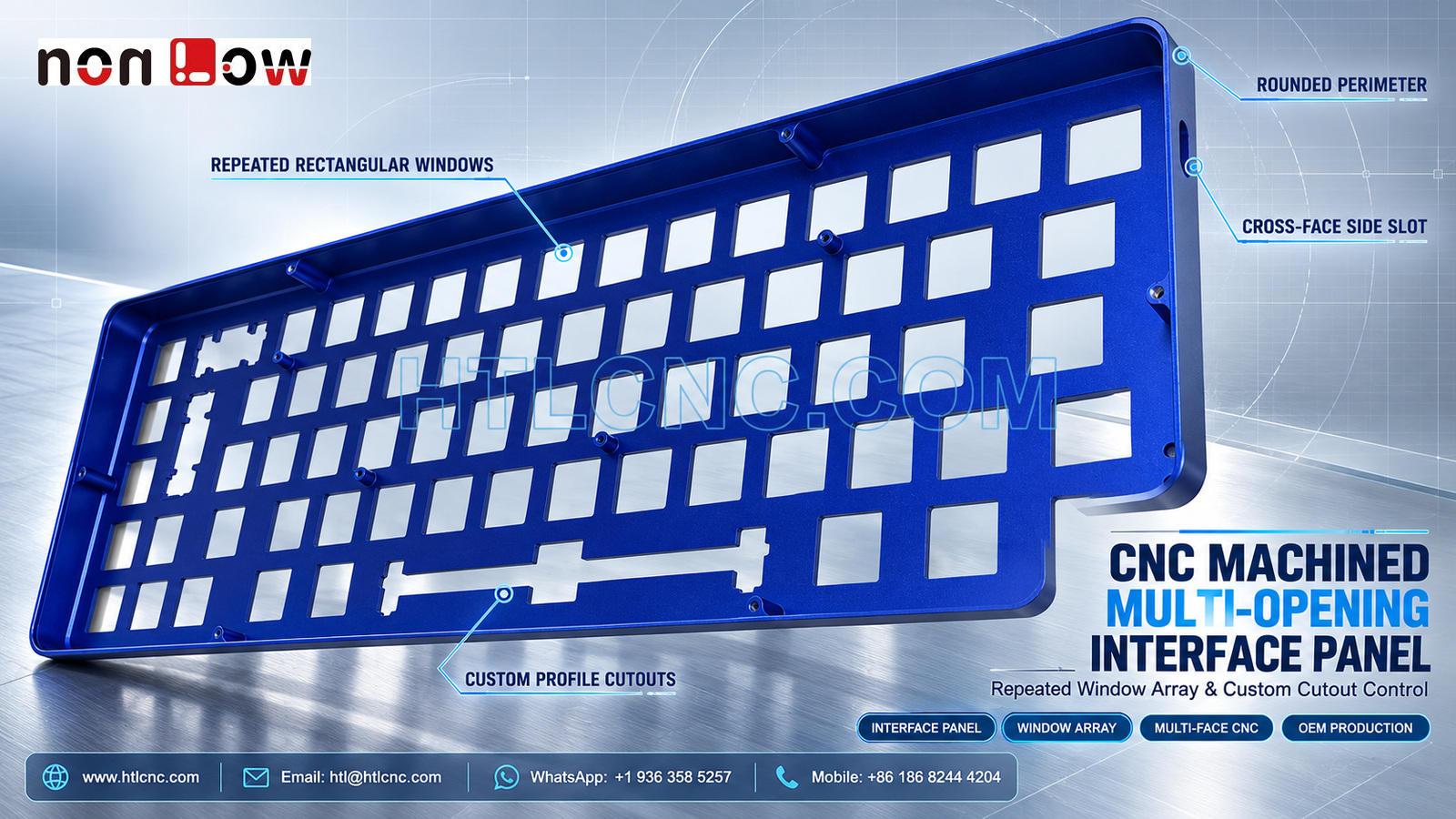
A CNC machined multi-opening interface panel housing combines a dense rectangular aperture field, custom profile cutouts, narrow connecting webs, rear mounting bosses and side-access features in one long enclosure component.
A CNC machined multi-opening interface panel housing combines dozens of repeated rectangular apertures with several custom profile cutouts, a rounded outside frame and a narrow side slot. Reverse-side source views also show a continuous perimeter wall, multiple mounting bosses and local support posts. The photographs do not establish the material grade, finish process, exact aperture function, tolerance class or final equipment application. HTL CNC provides drawing-based custom CNC machining for overseas OEMs, equipment builders, product-development companies, engineers and procurement teams from prototype qualification through repeat production.
Qualify the Part as a Two-Sided Housing, Not Only a Flat Faceplate
The front view is visually dominated by openings, but the reverse-side wall and bosses change the manufacturing scope. An RFQ should include the complete STEP model and controlled 2D drawing for both faces rather than a simplified DXF of the visible aperture pattern. Buyers should also provide mating-module envelopes, the installed orientation, exact material and finish, prototype and production quantities, annual demand, inspection-document requirements, packaging, destination and target schedule.
Supplier review should identify which front openings are functional interfaces, which rear bosses locate assemblies and which wall surfaces seat against the larger enclosure. HTL's custom CNC machining service uses that feature map to plan setups, datum transfer and inspection.
Build the Datum Structure from the Rear Seating Interface Forward
A long interface housing needs one coordinate system that connects front apertures, rear bosses, perimeter walls and side features. If the rear rim or selected pads establish the installed plane, the drawing should say so. A second and third datum can control lengthwise orientation and lateral clocking through qualified wall, boss or locating features.
Using only the outside silhouette as a shop reference may not prove that the aperture field aligns with the mounted modules. The first-article plan should reproduce the functional datum structure and state whether the component is measured free-state or on an approved support fixture.
Treat the Repeated Rectangular Apertures as an Engineered Field
The visible face contains many rectangular windows arranged in rows, yet the openings are not all identical. Size groups, row pitch, column pitch, internal corner radii, edge distances and intentional exceptions should be defined by feature identifiers or a controlled aperture schedule. This reduces ambiguity when a product revision changes only selected locations.
Repeated rectangular aperture machining must control both each opening and the accumulated pattern. A single window can meet width and height while the overall field drifts, rotates or changes pitch relative to the rear mounting system. Optical measurement or CMM data may be useful for a dense first article, followed by a risk-based production sampling plan.
Protect the Narrow Webs Between Openings
Material left between adjacent windows forms a network of narrow webs. Their width and straightness may influence appearance, local stiffness and alignment with customer-defined inserts. Cutting sequence, tool direction, heat and clamp force can affect these slender regions, especially after most surrounding stock has been removed.
Process planning may retain support longer during roughing, distribute material removal across the panel and finish critical edges after the frame is stable. Deburring should remove sharp material without thinning the webs, rounding window corners or leaving inconsistent borders across the visible pattern.
Separate Custom Profile Cutouts from the Regular Window Pattern
Several elongated and stepped openings interrupt the rectangular field. Their functions cannot be inferred from appearance. The drawing should define complete profiles, local tabs, reliefs, internal radii, orientation and relationship to the main aperture coordinate system. If a connector, switch module or customer-supplied insert fits one of these openings, include its envelope and installation path.
Custom profile cutouts may require smaller tools or additional contour passes than the regular windows. The quotation should therefore reflect actual corner access, edge requirements and inspection effort rather than counting every opening as an identical rectangular pocket.
Register Rear Mounting Bosses to the Front Interface Field
Reverse-side photographs show several raised bosses and posts. Their diameter, height, bore, thread and purpose must come from the released drawing. If they secure modules that pass through the front openings, boss position and height should be inspected relative to the same functional datums used for the matching aperture group.
Thread gauges confirm thread acceptance but not boss location or common mounting-plane height. A first article may combine thread and pin gauges with height measurement, CMM inspection and a customer-approved module fixture. This verifies that fasteners can start without forcing the installed component sideways.
Control the Perimeter Wall and Rounded Outside Frame
The component has a rounded rectangular perimeter and visible wall depth. The drawing should distinguish the cosmetic front rim, rear seating edge, wall profile and ordinary clearance surfaces. Wall thickness, height, corner transitions, overall twist and flatness requirements should be stated only where assembly needs them.
If clamp pressure temporarily straightens the long housing, measurements taken only in the fixture can hide free-state movement. Inspection should follow the drawing condition and confirm the assembly interface after unclamping when appropriate.
Plan the Cross-Face Side Slot and Other Edge Features
A narrow slot is visible on the outside edge. Its function is unknown, but its position, size, corner shape and relation to the front and rear geometry may require a controlled secondary setup. The complete model should include every edge opening so tooling and fixture hardware do not block access.
Depending on the tolerance network and quantity, the route may use indexed workholding, a rotary setup, 5-axis CNC machining or another qualified method. Axis count is not a quality claim; the important point is a documented transfer reference between front, rear and side machining.
Specify Material and Surface Appearance Without Relying on Color
The source group includes blue and light metallic examples, but image color does not prove material, anodizing, paint, plating or another treatment. The purchase documents should state material standard and condition, approved alternates, finish process, color and gloss limits, texture, masking zones, cosmetic areas and certificate requirements.
Where finish buildup affects aperture fit, boss threads or seating surfaces, the drawing should state whether dimensions apply before or after treatment. Approved appearance samples and defined viewing conditions can reduce disputes across a large visible face with many edges.
Validate the Prototype with Real Modules and Fasteners
A prototype should be trial-fitted with the modules, switches, inserts, connectors, fasteners and enclosure surfaces that interact with the aperture field and rear bosses. The engineering team can then check front alignment, insertion clearance, boss engagement, wall seating, side-slot access and tool reach in one assembly review.
HTL's prototype and low-volume CNC machining service supports engineering samples and pilot lots before dedicated fixtures and production sampling plans are locked. Approved changes should update the STEP model, 2D drawing, aperture schedule, boss table and inspection plan under one revision.
Lock Feature Maps and Inspection Records for Repeat Supply
Repeat production should control stock source, CNC program revision, fixture identity, datum-transfer method, tool-life limits, deburring standard, first-piece approval and sampling frequency. A revision affecting one irregular cutout or boss should identify the linked mating module and inspection characteristic so obsolete layouts are not mixed into a later release.
Packaging may use protective film, flat separators, sleeves or formed trays according to the finish and wall stiffness. Parts should not carry transport load through narrow webs or projecting bosses. Labels should identify part number, revision, quantity and production lot for receiving inspection and traceability.
RFQ Checklist for a Multi-Opening Interface Panel Housing
Send the released 2D drawing and full STEP file, assembly orientation, mating-module models, aperture schedule, boss and thread table, exact material and finish, prototype and repeat quantities, annual demand, functional datums, web-width requirements, custom cutout definitions, perimeter-wall and side-slot controls, cosmetic zones, inspection-document scope, packaging, destination and delivery target. Confidential files can be reviewed under the buyer's document-control process.
This package allows HTL CNC to quote the CNC machined multi-opening interface panel housing as one coordinated front, rear and cross-face manufacturing program. For a related enclosure topic with a large display opening rather than a dense window field, see our guide to CNC machined display control panel bezel sourcing.
Website: www.htlcnc.com Email: htl@htlcnc.com WhatsApp: +1 936 358 5257 Mobile: +86 186 8244 4204
Have a part ready for engineering review?
Send your drawing, STEP file, material and quantity directly to HTL CNC for a manufacturing quotation.