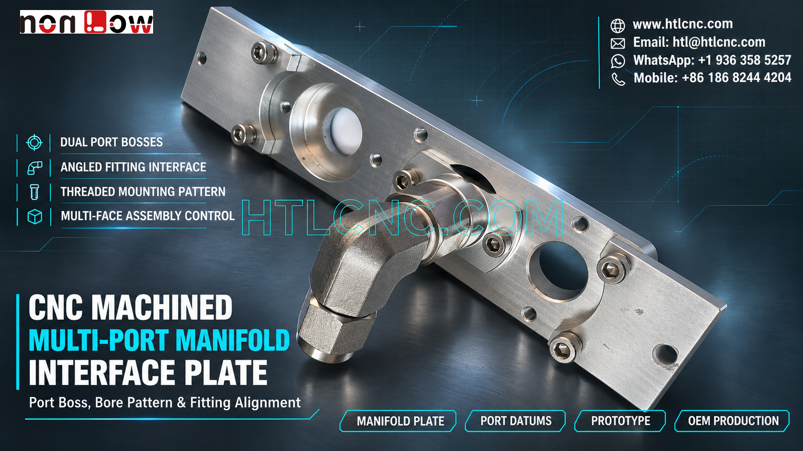
A CNC machined multi-port manifold interface plate combines raised circular port faces, a large bore, an angled fitting, threaded mounting features and a long plate datum that must remain coordinated for prototype validation and repeat OEM supply.
A CNC machined multi-port manifold interface plate brings several assembly relationships into one long machined component. The selected photograph clearly shows two raised circular port regions, one large open bore, one white-capped circular feature, a central angled metal fitting, multiple socket-head fasteners and threaded mounting holes. Those visible details support a manifold-interface topic, but they do not establish the working medium, internal passage layout, material, pressure rating, seal design, finish or final equipment. HTL CNC provides drawing-based custom CNC machining for overseas OEMs, equipment builders, engineering teams and procurement organizations from prototype review through repeat production.
Start the RFQ with the Interface Map, Not the Photograph
A supplier needs to know which port receives a fitting, which face locates the plate, which holes mount the assembly and whether any internal passages connect the visible features. The buyer should provide the released 2D drawing, complete STEP file, a labeled port schedule, mating components, specified material and condition, quantity, tolerances, finish, inspection scope and delivery destination.
If the plate handles air, hydraulic fluid, coolant, gas, vacuum or another medium, identify it explicitly together with customer-defined operating conditions, cleanliness requirements and validation method. These details cannot be inferred from the visible elbow fitting. HTL's custom CNC machining service reviews datum selection, workholding, tool access, drilling sequence and measurement access against the controlled engineering package.
Build One Datum Structure Along the Long Plate
The component's length makes datum strategy important. A primary mounting face, a longitudinal edge or centerline and a clocking feature can establish a common coordinate system for the two port regions, central fitting and surrounding holes. The actual scheme must follow the customer's drawing and assembly needs.
Programming every feature from a convenient local edge can produce acceptable individual dimensions while allowing the port pattern to drift across the plate. First-article inspection should reproduce the functional datum structure and report the relationships that affect fit. If plate flatness matters, the drawing should also state whether it is measured free-state, on specified supports or in an approved fixture.
Control Raised Port Faces and Bore Geometry Together
The photograph shows circular raised regions around the two main interfaces. The drawing should define each bore or cap seat, raised-face diameter, height, flatness, surface condition, concentricity or position, transition radii and edge treatment. If a gasket, O-ring, ferrule, plug or threaded component is involved, provide the mating geometry and applicable seal specification rather than relying on a generic surface-finish note.
The open bore and the capped feature may have different functions, so they should not automatically share one tolerance or inspection method. Depending on the released requirements, verification can combine bore gauges, height measurement, CMM probing, optical profile inspection and customer-approved mating parts. A measured diameter alone does not prove that the face and bore align with the rest of the assembly.
Treat the Angled Fitting as an Assembly Interface
The central metal fitting projects from the plate at an angle and occupies significant installation space. Its exact type and function are not confirmed by the image. The engineering package should identify the port thread or seat, insertion depth, orientation, tightening method, wrench clearance, permitted clocking range and whether the fitting is supplied by the customer or installed by the machining supplier.
The fitting can pass an individual thread check and still interfere with a neighboring part after assembly. Prototype review should therefore confirm thread engagement, final angle, tool access, tube or hose clearance where applicable and removal path. If torque or sealant is controlled, the purchase order should state the approved product, application method, torque value, curing condition and inspection record required.
Define Hidden Passages and Intersections from Controlled CAD
A manifold interface plate may contain drilled or milled passages, but the photograph does not reveal the internal route. The drawing and model should identify every passage diameter, depth, intersection, plug location, minimum remaining wall and breakthrough condition. Cross-drilled features need a sequence that protects positional relationships and permits reliable chip removal.
Where two holes intersect, an inaccessible burr can restrict flow, damage a seal or release contamination later. The manufacturing plan may include controlled drilling, deburring, flushing, borescope review or another customer-approved cleanliness method. Inspection should distinguish dimensional acceptance from functional flow or leak testing; both require defined criteria.
Coordinate Threaded Holes, Fasteners and Mounting Pattern
Several threaded holes and socket-head fasteners are visible around the port features and plate ends. Their exact roles are unknown, so the hole schedule should state thread form, class or fit, usable engagement, drill depth, counterbore or spotface, entry chamfer, positional tolerance and gauge requirement.
A thread gauge confirms thread condition but not pattern location or perpendicularity. When several holes secure one mating module, CMM results or a customer-approved fixture can verify the complete pattern. Fastener-head clearance, driver access and edge distance should also be checked during the prototype assembly rather than after production quantities are released.
Plan Multi-Face Machining and Back-Side Access
Other views in the source group show plate thickness, rear-side hardware and features that approach from different directions. A stable route may use qualified refixturing, indexed machining or another multi-face process according to tolerance, access, quantity and fixture rigidity. Machine-axis count should be selected from the actual relationships, not used as a generic quality claim.
The process plan should identify which face establishes the primary location, which features are completed before the plate is turned, and how critical datums are transferred. Probe routines, qualified stops or dedicated fixture nests can support repeatability, but final acceptance still depends on measured part results and functional assembly evidence.
Keep Pressure, Leak and Flow Testing Customer-Defined
No pressure rating or leak requirement can be assigned from the photograph. If the finished plate forms part of a fluid, pneumatic, vacuum or gas system, the buyer should specify the test medium, pressure or vacuum level, hold time, temperature, allowable leakage, port closures, fixture, safety controls and required report.
Dimensional inspection does not replace a functional test, and a functional test does not replace dimensional evidence. The RFQ should state whether testing occurs before or after surface treatment and fitting installation, and whether every unit or only a defined sample is tested.
Specify Material, Finish and Protected Surfaces
The light metallic appearance does not prove an alloy or treatment. Provide the exact material specification and condition, as-machined requirements or finishing standard, color and cosmetic zones, coating allowance, masking locations and certificate scope. Port faces, threaded regions, bores and electrical-contact areas may require different protection.
If coating thickness affects a fitting or seal, the drawing should state whether the dimension applies before or after treatment. An approved appearance sample can help define color and texture, but it should supplement written criteria rather than replace them.
Make Cleanliness and Packaging Part of Supplier Approval
Internal holes, blind threads, fitting seats and passage intersections can retain chips, cutting fluid or finishing residue. Define the required cleaning process, prohibited contaminants, inspection method and handling controls. Where cleanliness is critical, the customer may specify particle limits, rinse validation or protected assembly conditions.
Packaging should prevent the angled fitting, raised port faces and plate edges from carrying impact loads. Caps, plugs, formed trays, nonabrasive separators or individual wrapping can be selected from the finish and shipment route. Labels should connect part number, drawing revision, quantity and lot to the relevant inspection and test records.
Validate the Complete Assembly Before Repeat Production
Prototype evaluation should use real mating parts whenever possible. Engineering teams can check plate seating, port alignment, fitting angle, wrench access, fastener engagement, tube or hose clearance where relevant, and customer-defined leak or flow performance. Any change should be released through matching 2D drawing and STEP revisions before pilot production.
HTL's prototype and low-volume CNC machining service supports engineering samples and pilot lots before fixtures, test methods and sampling plans are locked. A related guide to multi-port manifold cavity-block machining explains additional considerations for sealing ledges and cross-face alignment in compact manifold-style components.
After approval, controlled raw material, fixture identification, CNC program revision, tool-life rules, first-piece checks, fitting-installation instructions, cleanliness controls and formal change management support repeat-order consistency. Annual demand and order cadence help the supplier plan material, machining capacity, finishing, inspection and export delivery.
RFQ Checklist for a Multi-Port Manifold Interface Plate
Send the released 2D drawing and STEP model, labeled port schedule, internal-passage definition, mating components, exact material, prototype and production quantities, annual demand, functional datums, bore and raised-face requirements, complete thread table, fitting specification and orientation, finish and masking notes, cleanliness criteria, pressure or leak test method where required, inspection report scope, packaging and delivery destination.
HTL CNC can then review the actual CNC machined multi-port manifold interface plate as a controlled machining, assembly, inspection and delivery program rather than guessing hidden function from a photograph. For engineering review and quotation, visit www.htlcnc.com, email htl@htlcnc.com, send WhatsApp to +1 936 358 5257, or call mobile +86 186 8244 4204.
Have a part ready for engineering review?
Send your drawing, STEP file, material and quantity directly to HTL CNC for a manufacturing quotation.