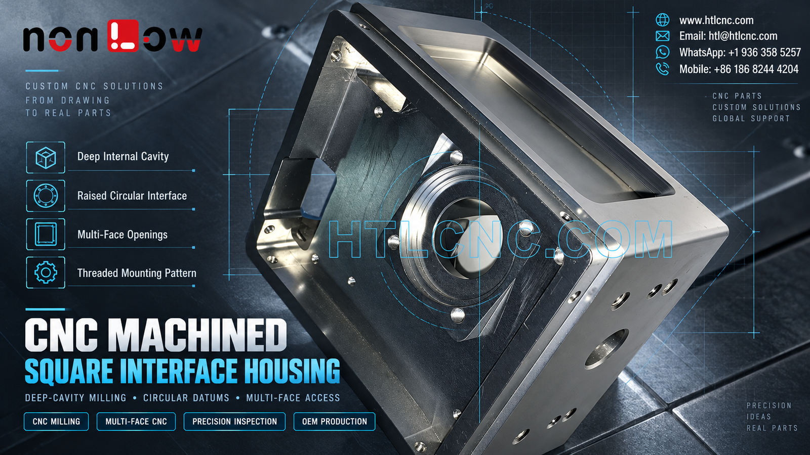
A CNC machined square interface housing combines a deep open cavity, raised circular interface, mounting-hole pattern and openings on adjacent faces that must remain related through a controlled datum plan.
A CNC machined square interface housing brings cavity milling, circular feature control and adjacent-face access into one compact structure. The selected photograph visibly shows a square housing with a deep open cavity, a raised circular interface and central through-bore, surrounding mounting holes, a large opening on the upper face and additional holes on a side wall. The image does not establish the material grade, tolerances, surface treatment, sealing function or end application. Those requirements must come from the buyer's released 2D drawing, STEP model and assembly specification. HTL CNC provides drawing-based custom CNC machining for overseas OEMs, equipment builders, R&D companies, contract manufacturers, engineers and sourcing teams from prototype validation through repeat production.
Qualify the Housing Around Its Functional Interfaces
Supplier qualification should begin with the interfaces that locate the housing in the customer's assembly. The drawing should identify the primary mounting face, the circular locating diameter or bore, a secondary plane, and the feature that controls rotation. Hole positions, side ports and cavity details can then be related to this datum structure instead of being dimensioned from unrelated stock edges.
Buyers should include mating-part data when the circular interface receives a shaft, lens, bearing, tube, connector or another component. The possible applications listed here are only examples; the photograph does not prove any one of them. HTL's custom CNC machining service reviews the released interface requirements before selecting machines, fixtures and inspection methods.
Control the Raised Circular Interface as a Complete Feature
The visible circular interface includes a central through-bore, stepped faces and a surrounding mounting pattern. Bore diameter alone may be insufficient when assembly also depends on roundness, cylindricity, surface finish, face runout, step height or perpendicularity to a mounting plane. The released drawing should distinguish locating diameters from clearance or cosmetic geometry.
Where practical, critical circular surfaces can be finished from one controlled orientation. If the part must be transferred, a qualified fixture should reproduce the established datum without clamping on a sensitive bore edge or finished face.
Plan Deep-Cavity CNC Milling for Tool Access and Stability
The open interior visibly removes a substantial volume while leaving wall sections around the perimeter. A deep-cavity CNC housing requires planning for cutter reach, tool stiffness, chip evacuation, corner radii and progressive material removal. Hidden shelves, undercuts or backside geometry in the complete model may further affect the route.
A balanced roughing strategy can leave support near thin walls and the raised interface before finishing critical surfaces. The exact sequence depends on stock condition, material, cavity depth, tolerance and quantity. Procurement teams should therefore avoid requesting a fixed process from appearance alone.
Keep Openings on Adjacent Faces in One Datum Chain
The upper rectangular opening and visible side-wall holes introduce more than one machining orientation. Their location may need to remain related to the internal cavity and circular interface. A process route may use controlled reclamping, indexed 4-axis work, 5-axis positioning or another qualified arrangement according to tolerance and production volume.
HTL's 5-axis CNC machining capability can be evaluated when reducing datum transfers or improving tool access is useful, but the final machine choice follows the released geometry and inspection plan rather than a marketing label.
Specify the Threaded Mounting Pattern Completely
Several visible holes appear threaded, but the photograph cannot confirm thread standard, size, pitch, class or engagement depth. The drawing should define thread callouts, lead-in, minimum full-thread depth, bottom condition, insert requirements and acceptance gauge. Hole coordinates should reference the same functional datums used by the circular interface.
Thread inspection may combine calibrated gauges with depth checks and visual review of starts and exits. If finishing or inserts are applied later, the customer should state the final acceptance condition and any masking or plug requirements.
Manage Wall Thickness, Edge Breaks and Free-State Geometry
Cavity roughing and multi-face openings change local stiffness. Clamping force that appears harmless on solid stock can influence the released shape of a hollow housing. Fixture support should be distributed around stable regions while keeping cutters and probes clear of through-features.
The drawing should identify controlled wall thickness, permissible edge breaks, protected sealing or seating surfaces and surfaces that must not be rounded. Final flatness or profile requirements should be verified in the specified free or restrained condition.
Build First-Article Inspection Around Assembly Risk
A risk-based first-article report may include outer envelope, cavity depth, wall thickness, circular bore size and geometry, step diameters, face relationships, mounting-hole positions, thread acceptance, upper opening dimensions, side-hole positions and drawing-defined geometric tolerances. Each result should reference the approved revision and datum scheme.
CMM inspection, bore gauges, thread gauges, height systems, optical measurement and surface-finish equipment may be combined according to feature access and tolerance. Overseas buyers should state whether they require selected dimensions, a full first-article report, material documents, finishing certificates or lot-level inspection records.
Do Not Infer Material or Finish from the Photograph
The silver and dark appearance does not prove aluminum, steel, anodizing, plating or any specific treatment. The RFQ should provide the exact material standard and condition, heat treatment where applicable, surface process, coating allowance, masking zones, cosmetic criteria and certification scope.
If coating can affect the circular fit, threaded holes or mating faces, the drawing should state whether dimensions apply before or after treatment. Approved color and texture samples can support cosmetic requirements, but they do not replace dimensional acceptance.
Validate the Prototype with Real Mating Components
Prototype evaluation should confirm circular fit, seating-face contact, hole-pattern alignment, access through adjacent openings, fastener engagement, cable or component clearance where applicable, and the proposed inspection method. Any change should update the 2D drawing and STEP file under the same controlled revision.
HTL's prototype and low-volume CNC machining service supports engineering samples and pilot lots. After approval, locked programs, qualified fixtures, first-piece checks, tool-life rules and documented revision control help maintain repeat-order consistency.
Prepare a Complete RFQ for Repeat Supply
Send the released 2D drawing and STEP file, mating-part or assembly data, exact material, prototype and production quantities, annual demand, datum scheme, circular interface requirements, cavity and wall controls, thread specifications, multi-face feature relationships, surface finish, inspection-document scope, packaging, destination and delivery target. Confidential drawings can be reviewed under the buyer's required document-control process.
This information allows HTL CNC to quote the CNC machined square interface housing as a controlled manufacturing program rather than guessing from a photograph. Export packaging can then be selected to protect bores, edges and finished faces during transit.
Website: www.htlcnc.com Email: htl@htlcnc.com WhatsApp: +1 936 358 5257 Mobile: +86 186 8244 4204
Have a part ready for engineering review?
Send your drawing, STEP file, material and quantity directly to HTL CNC for a manufacturing quotation.