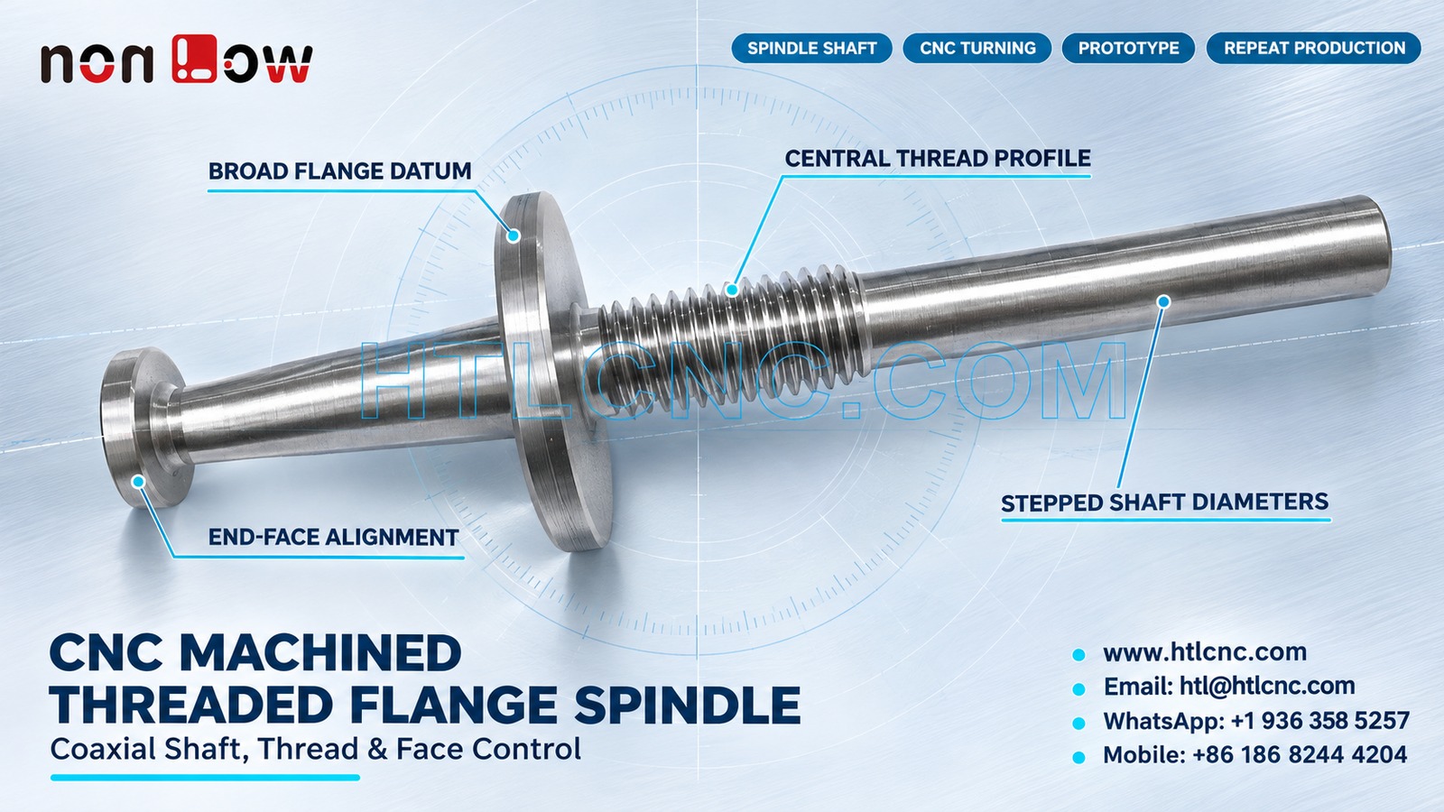
A CNC machined threaded flange spindle combines two shaft diameters, a central external thread, a broad flange and a smaller end flange that must remain coordinated for assembly, prototype validation and repeat OEM supply.
A CNC machined threaded flange spindle places several rotational features on one common axis. The selected photograph clearly shows a single long turned component with two cylindrical shaft sections, a central external thread, one broad flange, a smaller end flange and multiple stepped shoulders. Those visible details support a spindle-shaft machining topic, but they do not establish the material grade, thread standard, fit class, heat treatment, surface finish, load, speed or final machine. HTL CNC supplies drawing-based custom CNC machining for overseas OEMs, equipment builders, product-development teams and procurement organizations from prototype qualification through repeat production.
Start Supplier Review with the Mating Stack
A spindle cannot be qualified from its outside shape alone. The buyer should identify what fits each shaft diameter, what engages the external thread, which flange provides axial location, and whether the smaller end flange retains another component. Simplified mating envelopes or customer-approved sample parts help the supplier understand the functional stack without exposing unrelated assembly details.
A complete RFQ should include the released 2D drawing, STEP model, exact material and condition, thread specification, fit requirements, prototype and production quantities, annual demand, finish, inspection documentation, packaging and destination. HTL's CNC turning and turn-mill machining service reviews stock diameter, chucking, tool access, datum transfer and measurement strategy before quotation.
Establish One Functional Axis for Both Shaft Sections
The two cylindrical sections sit on opposite sides of the central flange and thread. Their individual diameters may be correct while their axes still differ after a poor second setup. The drawing should identify the functional datum axis and specify the relationship of each shaft section to that reference using the characteristic that matches the assembly.
Depending on the design, inspection may include diameter, roundness, cylindricity, coaxiality or runout. These terms are not interchangeable. A supplier needs the datum, measurement length, rotation method and acceptance criterion before building the process and first-article plan.
Control the External Thread from the Shaft Datum
The central external thread occupies a significant length of the component. The photograph does not reveal its form, pitch, class, hand, start count or intended mating nut. The drawing must state the complete thread definition, usable length, runout, lead-in chamfer, relief or undercut, surface condition and gauge method.
A ring gauge can confirm thread fit but does not prove that the pitch cylinder is aligned with the neighboring shaft diameters. When alignment affects assembly, first-article inspection should relate the thread to the functional shaft axis and flange face. A customer-supplied mating part can supplement, not replace, the controlled dimensional method.
Use the Broad Flange as an Axial Datum Only When the Drawing Says So
The broad central flange is the largest face feature and may appear to be the obvious axial reference. Its actual function is not confirmed by the image. The released design should identify whether this face locates an assembly, carries a clamp, provides clearance or serves another purpose.
If it is a functional seating face, the drawing may need face flatness, perpendicularity or runout relative to the shaft axis. Flange thickness and the axial distance to the end flange should be dimensioned from a consistent datum rather than accumulated through several local shoulder widths.
Coordinate the Smaller End Flange with the Axial Stack
The opposite end includes a smaller flange and stepped transition. The buyer should define outside diameter, face position, thickness, corner radius, edge break and any contact or retention function. If a component must pass over the shaft before seating against this flange, provide its bore, chamfer and installation direction.
A prototype assembly should confirm insertion, axial seating, tool clearance and removal. The supplier should not infer retention force, preload or torque from the flange appearance; those values require customer-defined mating hardware and test conditions.
Plan the Turning Sequence to Protect Coaxiality
Rotational geometry generally favors CNC turning, but the best operation sequence depends on stock, total length, material, tolerance and volume. A first operation may establish one shaft, the thread and broad flange from a common setup. A qualified second operation can complete the opposite end while locating from finished functional surfaces.
Long overhang can introduce deflection and chatter. Tailstock support, a steady rest, soft jaws or other workholding may be considered according to geometry and surface requirements. The process should control clamp force and support location so the finished spindle is not bent or marked.
Separate Diameter Fit from Surface Texture
A shaft diameter can meet size limits while its surface texture, waviness or tool marks prevent the intended fit or seal. The drawing should state which cylindrical surfaces are bearing seats, sliding fits, clearance regions or cosmetic areas, and assign finish requirements only where function supports them.
Inspection may combine micrometers, air gauges, roundness equipment, profilometry or customer-approved functional masters. Measurement temperature and stabilization can matter when fits are tight. Supplier and buyer should agree whether finish and diameter are accepted before or after any heat treatment or coating.
Define Material, Heat Treatment and Finish as Separate Requirements
The metallic appearance does not identify an alloy or process condition. The purchase order should specify material standard, condition, heat treatment, hardness, coating or passivation, protected surfaces and certificate scope. If heat treatment occurs after rough machining, the route may need stock allowance and final grinding or turning to recover size and runout.
Coating buildup can affect the thread, shaft fits and flange seating faces. Masking notes and post-finish dimensions should be explicit. A generic finish note should not force the supplier to guess which functional surfaces must remain uncoated.
Build First-Article Inspection Around the Complete Axis
A useful first-article report can cover both shaft diameters, the datum axis, external thread, broad flange thickness and face relation, smaller end flange, axial shoulder distances, runout and drawing-defined surface finish. The report should state part revision, material condition, finish stage, restraint method and equipment.
For another rotational component with stepped bores and flange relationships, review our guide to CNC machined flanged roller component control. That example focuses on internal geometry; this spindle requires its own axis and thread plan.
Validate the Prototype with Real Mating Parts
Engineering samples should be checked with the intended nut, bearing, sleeve, hub, spacer or other mating hardware where applicable. The customer can verify insertion, thread engagement, axial seating, flange clearance and assembly tool access. Load, speed, fatigue, wear or thermal testing requires customer-defined fixtures and pass criteria.
HTL's prototype and low-volume CNC machining service supports sample and pilot quantities before dedicated jaws, gauges and sampling plans are finalized. Any approved change to the thread, shoulder, shaft diameter, material or finish should update the 2D drawing and STEP model under the same revision.
Lock the Accepted Process for Repeat Orders
Repeat supply depends on controlled raw material, chuck and jaw identification, CNC program revision, first-piece approval, tool-life limits, in-process diameter checks and final inspection sampling. Thread gauges and functional masters should be calibrated and linked to the current part revision.
Packaging should protect thread crests, flange faces and finished shaft diameters from metal-to-metal contact. Thread sleeves, formed trays, nonabrasive separators or individual wrapping can be selected according to finish sensitivity and export route. Lot labels should connect the part number, revision and quantity to inspection records.
RFQ Checklist for a Threaded Flange Spindle
Send the released 2D drawing and STEP file, simplified mating geometry, exact material and condition, complete external-thread specification, both shaft fits, functional datum axis, flange-face relationships, prototype and production quantities, annual demand, heat treatment, finish and masking notes, first-article scope, packaging, destination and delivery target. Confidential files can be reviewed under the buyer's required document-control process.
A complete package allows HTL CNC to quote the CNC machined threaded flange spindle as a controlled turning, threading, finishing and inspection program rather than guessing fit or service conditions from a photograph. For engineering review and quotation, visit www.htlcnc.com, email htl@htlcnc.com, send WhatsApp to +1 936 358 5257, or call mobile +86 186 8244 4204.
Have a part ready for engineering review?
Send your drawing, STEP file, material and quantity directly to HTL CNC for a manufacturing quotation.