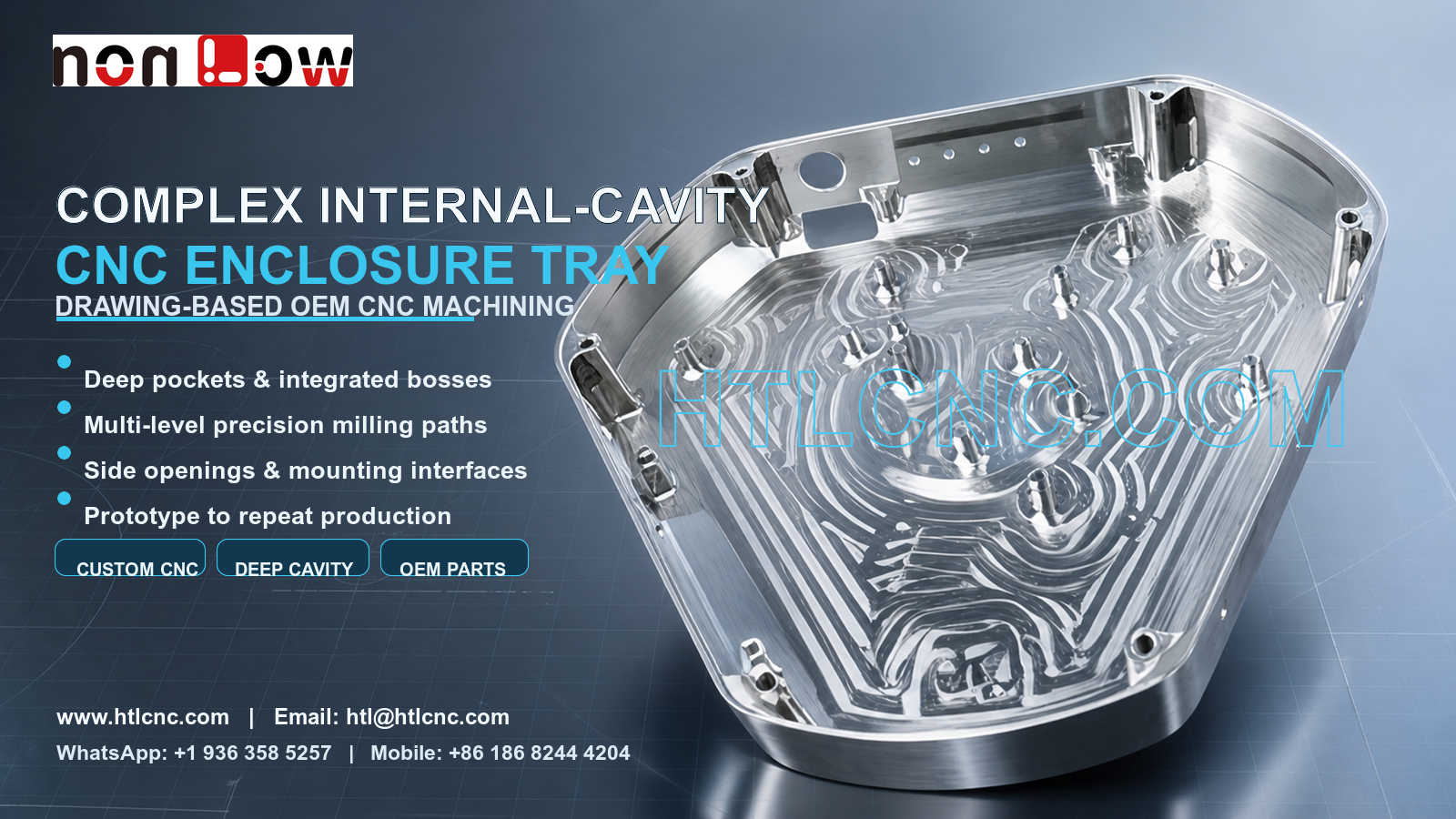
A complex internal-cavity CNC enclosure tray combines deep pockets, integrated bosses, multi-level milling paths and side interfaces in one drawing-based precision part.
A complex internal-cavity CNC enclosure tray brings sealing faces, internal support points, cable or connector openings and mounting features into one machined body. The pictured component visibly includes a deep perimeter wall, a broad contoured internal pocket, numerous integrated bosses, localized recesses and openings through the side structure. HTL CNC provides custom CNC machining and drawing-based OEM manufacturing for overseas equipment makers, engineering teams and procurement organizations that need precision CNC parts from prototype validation through low-volume production and repeat supply. Material grade, dimensional tolerance, sealing duty and final application cannot be established from a photograph and must be confirmed from the customer's released files.
Why Internal-Cavity Enclosures Require Early Engineering Review
An enclosure tray is not defined only by its outside shape. Its assembly performance may depend on the relationship between a perimeter mating face, internal mounting bosses, wall openings and a cluster of component interfaces. Before quotation, the customer and supplier should identify functional datums, critical mating zones, protected cosmetic surfaces and features that are only for clearance.
A complete review normally uses both a 2D drawing and a STEP model. The 3D model supports tool-access and workholding analysis, while the drawing controls dimensions, tolerances, threads, finish requirements and inspection notes. When several electronic, optical or mechanical items mount inside one tray, an assembly model or related-part drawing can clarify which bosses belong to the same positional group.
Deep-Pocket Milling and Material-Removal Strategy
The visible internal cavity contains a large amount of removed material and many changing levels. A practical machining plan may separate bulk roughing, semi-finishing and final finishing so that stock removal, heat generation and part stiffness are managed in stages. Tool diameter, reach, corner radius and chip evacuation must be checked against the actual CAD geometry.
Long tools can reach deep areas but may reduce rigidity. Smaller tools may access tight transitions but increase cycle time. The engineering team therefore reviews which internal corners are functionally required and which can accept a cutter-friendly radius. This is particularly important for OEM projects where a prototype design must later support repeat production at a controlled cost.
Integrated Bosses and Related Hole Positions
The machined floor includes multiple raised bosses and local pads. Depending on the released design, these features may support boards, sensors, covers, spacers or other internal components, but their exact use should not be inferred from the image. Their height, hole size, thread specification and position may form a related installation pattern.
Inspection should evaluate the group according to assembly function. Important characteristics can include boss height from the main datum, hole-to-hole position, thread depth, local flatness and the relationship to side openings. If a fastener or insert is specified, the RFQ should identify the hardware, engagement requirement and whether the feature is inspected before or after surface treatment.
Side Openings, Perimeter Face and Multi-Side Access
Openings around the enclosure wall add cross-face relationships to an already complex cavity. They may require additional orientations after the main pocket is produced. A qualified 3-axis route with controlled refixturing can be suitable for some designs, while indexed 4-axis or 5-axis CNC machining may reduce datum transfers when several side features must remain closely related. The number of axes is selected from access, tolerance, rigidity, volume and cost rather than used as a generic quality claim.
The perimeter face may become an assembly or sealing interface. Its flatness, width, hole pattern and surface condition should be specified when functional. Clamping and deburring must protect this face while side slots and holes are completed. Loose burrs inside an enclosure are unacceptable where they could affect assembly, cleanliness or later finishing.
Process Control from Prototype to Repeat Production
Prototype manufacturing should prove more than the ability to machine one visually acceptable part. The first build can be used to verify assembly clearance, boss alignment, side-interface access, cover fit, finish allowance and packaging protection. Any change should be released through a controlled drawing and model revision before production ramp-up.
For repeat orders, approved programs, qualified fixtures, tool-life controls, in-process checks and revision management help preserve consistency. Procurement teams can ask how the supplier identifies programs, segregates revisions, manages outside finishing and records first-piece approval. Annual demand, order cadence and delivery destination also influence fixture investment, machine loading and packaging design.
Inspection Evidence for a Precision CNC Enclosure Tray
An inspection plan should follow the functional dimension chain. Candidate checkpoints include overall profile, cavity depth, wall thickness where specified, perimeter-face flatness, boss height, hole position, thread condition, side-opening location, local pocket depth and drawing-defined geometric controls. Equipment may include calipers, micrometers, depth gauges, pin and thread gauges, height measurement, optical systems and CMM inspection according to access and tolerance.
During supplier onboarding, buyers may request a first-article inspection report, selected measurement records or a control plan for critical features. The reporting scope, sampling level, traceability and document-retention period should be agreed before quotation. This prevents a mismatch between the quality package expected by the customer and the evidence included in the production price.
Surface Treatment, Cleanliness and Packaging
The part may be delivered as machined or with a customer-specified treatment compatible with the released material. Possible processes can include anodizing, plating, passivation, blasting, brushing, polishing, painting or another controlled finish, but no option should be assumed from the photograph. Drawings should define masked mating faces, protected holes, plugged threads, coating allowance and cosmetic acceptance zones.
Deep cavities and threaded bosses require careful cleaning after machining and finishing. Packaging can use protective film, separators, individual wrapping or formed trays to prevent metal-to-metal contact. Labels should connect the part number, drawing revision, quantity and lot to the supplied inspection records.
RFQ Package for Drawing-Based OEM Manufacturing
Send the released 2D drawing and STEP file with material requirements, prototype and production quantities, annual demand, critical datums, boss and hole relationships, threads, surface finish, inspection-document needs, packaging expectations, required delivery date and destination. Include mating-part data when the perimeter face or side openings depend on related components. HTL CNC can then review the actual complex internal-cavity CNC enclosure tray and prepare a manufacturing and quality plan based on controlled requirements rather than assumptions.
Website: www.htlcnc.com Email: htl@htlcnc.com WhatsApp: +1 936 358 5257 Mobile: +86 186 8244 4204
Have a part ready for engineering review?
Send your drawing, STEP file, material and quantity directly to HTL CNC for a manufacturing quotation.