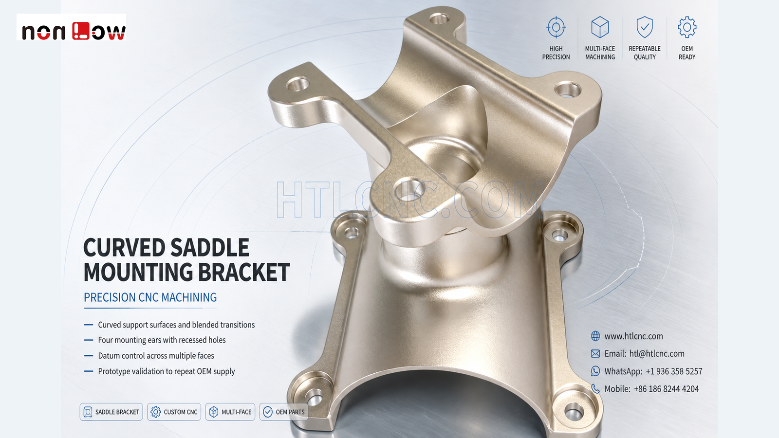
Curved saddle mounting bracket CNC machining coordinates broad support radii, blended ribs, recessed mounting holes and multi-level faces around a stable datum plan.
Curved saddle mounting bracket CNC machining is required when an OEM component must combine a broad concave support surface, blended structural transitions, multiple mounting ears and holes at different levels. The pictured single part visibly includes two curved cradle regions, four outer mounting points, recessed circular features, a central opening and smoothly connected walls. HTL CNC supports overseas equipment builders, product-development companies, engineers and procurement teams with custom CNC machining, precision CNC parts, multi-face milling, prototype validation, low-volume production and repeat drawing-based manufacturing. The image does not establish the material grade, tolerance, surface treatment, load rating or final application; those requirements must come from the customer's released 2D drawing, STEP model and assembly specification.
What Is a Curved Saddle Mounting Bracket?
A saddle bracket uses a concave or partially cylindrical surface to support or locate a mating body. Its function may depend on contact radius, seating length, mounting-hole position and the relationship between upper and lower levels. The photograph shows the geometry but cannot confirm whether the surface carries load, provides clearance or locates another component.
For supplier qualification, the OEM should identify the actual mating diameter, allowable contact condition and the datum that controls the saddle centerline. A mating-part model is especially useful because an apparently smooth radius can still create assembly interference if its center or orientation is referenced incorrectly.
Curved Surface Machining and Tool-Path Continuity
Broad curved surfaces may be produced through contour milling, ball-end finishing or another route selected from the surface definition, tolerance, finish and quantity. Tool paths should maintain consistent engagement through the radius and blended transitions. Abrupt direction changes can leave witness lines or local variation that matter when the surface is functional or visible.
The drawing should distinguish the true contact region from adjacent blend surfaces. If only part of the arc controls fit, inspection and finishing can focus on that defined zone rather than treating every sculpted surface as equally critical.
Four Mounting Ears Create a Datum Network
The part visibly includes four outer ears with recessed holes. These mounting points may establish attachment and orientation, but the image cannot identify which holes locate and which provide clearance. The released drawing should define hole type, size, depth and position from the selected datums.
When the ears sit at different heights or surround a curved body, the supplier must preserve their relationship to the saddle axis and seating faces. A hole can meet its individual diameter requirement while the pattern still fails assembly because its true position or face depth is referenced to the wrong surface.
Blended Ribs and Variable Wall Sections
The saddle regions merge into ribs, shoulders and outer lugs. These transitions distribute geometry but also create changing cutter access and workpiece stiffness. Roughing should retain enough support around the ears and thin transitions before the final curved surfaces and hole faces are completed.
Internal radii, wall thickness and blend requirements should be reviewed during manufacturability analysis. Practical radii allow stronger tools and stable passes, while unnecessary sharp transitions can increase tool reach and cycle time without improving assembly.
Multi-Face CNC Setup Strategy
The visible top holes, recessed faces, curved interiors and lower features require access from more than one direction. Depending on tolerance, stock form, quantity and part size, the route may use controlled 3-axis refixturing, indexed 4-axis machining or 5-axis CNC machining.
The process should keep the functional saddle axis and mounting-face datum traceable through each setup. Fixtures need to support rigid regions without marking finished surfaces or distorting the open geometry. More machine axes are useful only when they improve access or reduce uncontrolled datum transfer.
How Should the Saddle and Hole Pattern Be Inspected?
A risk-based inspection plan may cover the saddle radius or profile, its centerline relative to the mounting pattern, ear-face height, recessed-hole diameter and depth, hole position, overall envelope, wall transitions and drawing-defined geometric controls. Measurement can combine gauges, height systems, optical equipment, CMM scanning or probing and customer-approved functional fixtures.
A mating gauge may confirm practical contact or clearance, but it does not replace dimensional evidence when the drawing specifies profile, position or datum relationships. First-article records should identify the part number, released revision, production lot and measurement condition.
Surface Finish and Protected Interfaces
The bright appearance does not prove a material or finishing process. After the OEM defines material and service environment, possible options may include an as-machined condition, blasting, polishing, plating, passivation, anodizing, painting or another compatible treatment.
Coating-sensitive saddle regions, recessed holes and seating faces should be identified for masking, dimensional allowance or post-finish verification. If appearance matters, the drawing or approved sample should define cosmetic zones, texture direction and acceptable handling marks.
Prototype Validation and Repeat Supply
Prototype quantities allow the engineering team to verify mating-radius contact, hole-pattern alignment, fastener access, adjacent-part clearance, assembly orientation and the proposed inspection method. Load, vibration, wear or life tests require customer-defined procedures and acceptance criteria; no such performance can be inferred from the image.
After approval, HTL's prototype and low-volume CNC machining supports engineering samples and pilot quantities. The custom CNC machining service can then support repeat OEM production through controlled programs, qualified fixtures, first-piece checks, revision control, inspection documentation and export packaging.
RFQ Checklist for a Curved Saddle Bracket
Send the released 2D drawing, STEP file and mating-part or assembly model. Include material, prototype quantity, production quantity or annual demand, functional saddle and mounting datums, hole and recess definitions, tolerances, surface finish, inspection-document scope, revision status, packaging, destination and target schedule. HTL CNC can then review the curved saddle mounting bracket CNC machining project and prepare a controlled manufacturing and quality plan.
Website: www.htlcnc.com Email: htl@htlcnc.com WhatsApp: +1 936 358 5257 Mobile: +86 186 8244 4204
Have a part ready for engineering review?
Send your drawing, STEP file, material and quantity directly to HTL CNC for a manufacturing quotation.