Custom CNC machining across diverse part geometries requires drawing-led process selection, stable datum planning, feature-specific inspection and disciplined revision control from prototypes to repeat OEM supply.
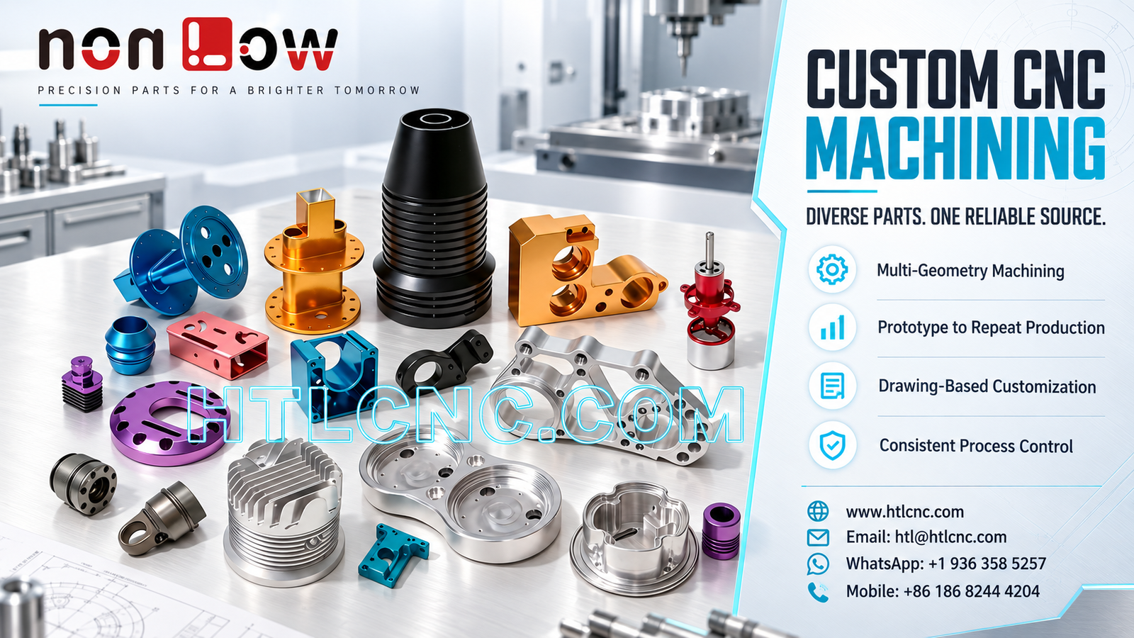
Custom CNC machining programs often include much more than one part family. The pictured collection shows circular components, housings, brackets, frames, finned forms, deep pockets, bores, hole patterns and multi-level surfaces in several visible colors and finishes. It demonstrates geometric variety, but the image does not identify material grades, coating processes, tolerances, end uses or whether the parts belong to the same assembly. Those requirements must come from the buyer's released drawings, 3D models and specifications. HTL CNC supports overseas equipment builders, product-development teams, contract manufacturers, engineers and procurement teams with drawing-based CNC machining, prototype validation, low-volume builds and repeat OEM production.
Why a Mixed-Part RFQ Needs Structured Review
A package containing turned, milled and multi-face parts should not be treated as one generic machining request. Each part number needs its own geometry review, material callout, quantity, revision, functional datums, critical features, finish requirement and inspection scope. A supplier can then group compatible work without losing control of part-specific requirements.
The RFQ should include a released 2D drawing and STEP model for every item. A bill of materials or part matrix can connect part number, revision, quantity, material, finish, inspection level and delivery priority. This structure reduces ambiguity when several visually similar parts have different internal features or acceptance criteria.
Selecting the Machining Route by Geometry
Round parts with concentric diameters, faces and grooves may be suited to CNC turning or turn-mill processing. Prismatic housings, brackets and plates may require 3-axis or indexed milling. Components with features distributed across several orientations may benefit from 4-axis positioning or 5-axis CNC machining, depending on access, rigidity, tolerance and quantity.
Machine selection should follow the released geometry rather than a marketing label. HTL's custom CNC machining service can combine appropriate turning, milling and secondary operations within one controlled supply program while keeping each part number tied to its approved process plan.
Datum Planning Across Different Feature Types
A circular component may locate from a bore and seating face, while a bracket may depend on a broad base surface and two mounting holes. A housing may require control between an outer profile, internal pocket and hole pattern. The drawing should identify functional datum features and define geometric relationships where assembly depends on alignment.
Clear datum planning helps the machining team choose workholding, setup sequence and inspection references. It also prevents dimensions from being checked independently when the assembled relationship is what matters. Thin walls, open frames and interrupted shapes may need additional support or staged material removal to limit movement during machining.
Pockets, Bores, Threads and Edge Conditions
The image visibly includes deep cavities, circular bores, small holes, slots, ribs and curved transitions. Each feature introduces different tool-access and verification questions. Deep pockets require review of cutter reach and chip evacuation. Bores may need controlled size, roundness or positional relationships. Small holes and threads need defined depth, thread standard and exit condition.
Internal corners normally retain a cutter radius, so a drawing should not imply a sharp corner unless a specific manufacturing method is required. Edge breaks, chamfers and deburring instructions should distinguish functional interfaces from cosmetic edges. A general note should not unintentionally round a locating shoulder or alter a small opening.
Materials and Finishes Must Be Confirmed
Visible silver, black, blue, gold, red and purple surfaces do not prove any particular alloy, resin, anodizing, plating, paint or heat treatment. Color alone is not a material or finish specification. Buyers should provide the exact material standard, temper or condition where applicable, approved finish process, color reference, masking zones, coating allowance and certification requirements.
Finish planning should account for threaded holes, close-fit bores, electrical contact areas and cosmetic surfaces. If coating thickness can affect assembly, the drawing should state whether dimensions apply before or after finishing. Approved limit samples may help align visual expectations when appearance is important.
Inspection for a Diverse CNC Parts Package
Inspection should be risk-based rather than identical for every component. A practical plan may include outside dimensions, bore sizes, pocket depths, hole position, thread verification, face relationships, flatness, profile or runout only where required by the drawing. Measurement methods can include calibrated hand tools, pin and thread gauges, height systems, optical equipment and CMM inspection according to feature access and tolerance.
Reports must identify the exact part number and revision. For prototype qualification, the buyer should specify whether selected dimensional results, a first-article report, material certificates, finish records or assembly evidence are required. Repeat production can then use an agreed sampling plan and lot-linked records.
Prototype Validation and Revision Control
Prototype builds allow engineering teams to check fit, fastener access, clearance, edge condition and mating relationships before releasing repeat quantities. If testing changes a bore, mounting pattern, pocket, material or finish, both the 2D drawing and 3D model should be updated together. Superseded files should be removed from active production control.
After approval, controlled programs, qualified fixtures, first-piece checks, approved external processes and formal change management support low-volume ramp-up and repeat supply. HTL's prototype and low-volume CNC machining service supports this staged route.
Packaging and Delivery Across Multiple Part Numbers
Mixed-part orders need clear identification and physical separation. Labels should show part number, revision, quantity and production lot. Protective sleeves, separators, trays or individual wrapping may be selected according to geometry and finish so heavier components do not damage delicate edges or cosmetic faces.
Procurement teams should provide annual demand, release frequency, destination and target schedule. This helps the supplier plan material, machine capacity, external finishing, inspection workload and export packaging without mixing revisions or configurations.
RFQ Checklist for Diverse Custom CNC Parts
Send the released 2D drawings and STEP files, a part-number and revision matrix, exact material and finish specifications, prototype and production quantities, annual demand, functional datums, critical features, tolerances, edge requirements, inspection-document scope, packaging, destination and delivery schedule. Include mating-component models when fit or alignment is critical. HTL CNC can then review the complete custom CNC machining package and propose a controlled manufacturing, quality and supply plan.
Website: www.htlcnc.com Email: htl@htlcnc.com WhatsApp: +1 936 358 5257 Mobile: +86 186 8244 4204
Have a part ready for engineering review?
Send your drawing, STEP file, material and quantity directly to HTL CNC for a manufacturing quotation.