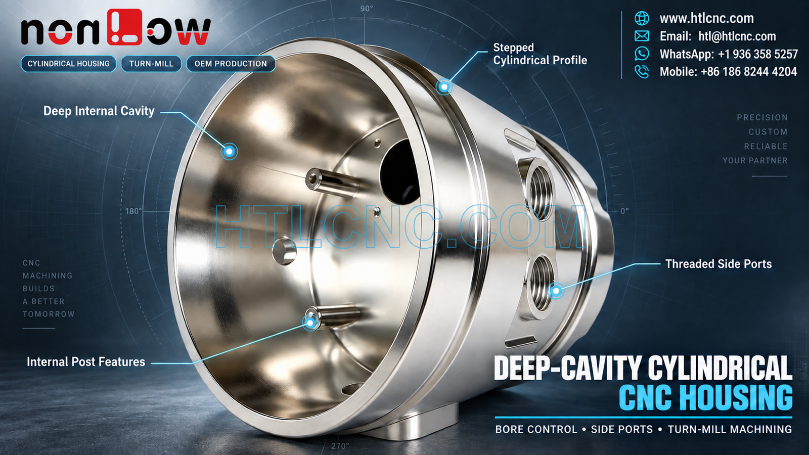
A deep-cavity cylindrical CNC housing combines a broad internal bore, stepped outside diameters, internal post features and threaded side ports that must remain related to one functional axis.
A deep-cavity cylindrical CNC housing can combine turned diameters with milled and threaded features in one compact component. The pictured part visibly includes a large front rim, a deep internal cavity, a stepped outside profile, two side ports, internal post-like features, several internal holes and a rear flange area. The image does not establish the material grade, bore tolerance, thread specification, sealing requirement, surface treatment or final application. Those requirements must come from the buyer's released drawing, 3D model and assembly information. HTL CNC supports overseas OEMs, equipment builders and engineering teams with drawing-based cylindrical housing machining, prototypes, low-volume builds and repeat production.
Start with the Functional Cylindrical Datum
For a housing built around a deep cavity, the RFQ should identify which bore, outside diameter or face establishes the primary axis. The front rim, internal floor, rear profile and side ports may all need to relate to that axis, but appearance alone cannot define the functional datum. Basic dimensions and geometric tolerances should state the required relationships.
A stable datum strategy helps machining and inspection use the same coordinate system. HTL's custom CNC machining service reviews the released drawing, model and mating information before selecting workholding and measurement methods.
Deep-Bore Access, Tool Reach and Internal Features
A deep internal cavity changes tool access, chip evacuation and inspection reach. The drawing should define bore diameter, cavity depth, floor geometry, corner radii, allowable tool marks and any coaxiality, runout or profile controls. Internal posts and smaller openings should be numbered so that their size, height and location are not confused during production or inspection.
Long tools can reduce rigidity, while trapped chips may mark a finished floor or wall. A practical route may rough the cavity with a stable tool, leave controlled stock, clear chips, then finish the bore and datum faces under measured cutting conditions. The actual sequence depends on geometry, material, tolerance and quantity.
Control the Stepped Outside Profile and Front Rim
The visible outer body includes several stepped cylindrical regions and a broad front rim. If those surfaces locate the housing, support a mating component or define assembly clearance, the drawing should specify diameter, face position, runout and edge-break requirements. Cosmetic reflectivity is not a substitute for a surface-finish callout.
Turning can efficiently establish concentric diameters and faces when the geometry and stock allow. Milling or indexed work may then create flats, openings and port features. HTL's CNC turning and turn-mill machining supports parts that combine rotational geometry with off-axis details.
Locate Threaded Side Ports from the Main Axis
Two threaded side ports are visible on the body, but their thread standards, depths and functions cannot be confirmed from the image. The 2D drawing should define thread type and class, drill depth, full-thread depth, port angle, axial position and orientation around the housing. If a port intersects the cavity, the drawing should also identify internal edge-break and cleanliness requirements.
A port can pass a thread gauge while still being incorrectly positioned relative to the bore or mating line. Inspection should therefore separate thread acceptance from coordinate position and angular orientation. For restricted access or several indexed features, 5-axis CNC machining may reduce refixturing, although machine selection should follow the complete model and tolerance plan.
Plan Turning, Milling and Refixturing Together
A cylindrical housing may be produced on a lathe plus a machining center, on turn-mill equipment or through another qualified route. The best choice depends on stock form, cavity depth, side-feature access, batch size and required datum relationships. The process plan should protect finished bores and faces when the part is transferred between operations.
If refixturing is necessary, qualified diameters or purpose-machined locating surfaces can transfer the datum system. Clamping forces should avoid distorting a thin rim or marking an approved cosmetic surface. First-piece verification after unclamping is important when roundness, runout or face relationships are critical.
Deburr, Clean and Inspect Internal Intersections
Deep cavities and intersecting side ports can retain chips, cutting fluid and burr fragments. The drawing or purchase specification should state cleanliness, edge-break and prohibited-contamination requirements when they matter to assembly. Deburring must not enlarge a thread entrance, round a locating edge or change an internal post dimension.
A risk-based first-article inspection may cover the primary bore and depth, front-rim diameter and face, stepped outside diameters, internal floor and opening locations, post height and position, side-port threads, port coordinates and drawing-defined geometric controls. Depending on access, measurement may combine bore gauges, depth tools, thread gauges, height systems, optical inspection and CMM methods.
Material and Finish Must Come from Released Data
The bright metallic appearance does not prove aluminum, stainless steel, nickel plating, anodizing, passivation or polishing. The RFQ should provide the exact material standard and condition, permitted substitutions, heat treatment, finish, coating allowance, masking zones and certification scope. Critical bore, thread and seating dimensions should state whether they apply before or after finishing.
Prototype Assembly Checks and Repeat Production
Prototype housings let the OEM team verify mating diameter, insertion depth, side-port alignment, internal clearance, fastener access and assembly orientation with actual components. If leak performance, sealing or pressure service is relevant, the customer should provide the applicable interface design and test requirement; these functions are not inferred from the photograph. HTL's prototype and low-volume CNC machining service supports engineering samples before recurring releases.
After approval, revision-controlled programs, qualified fixtures, tool-life rules and inspection records help preserve the accepted geometry. Packaging should protect the front rim, bore surface, side threads and cosmetic areas from impact or metal-to-metal contact. Labels should identify part number, revision, quantity and production lot.
RFQ Checklist for a Deep-Cavity Cylindrical CNC Housing
Send the released 2D drawing and STEP file, mating models and assembly orientation, exact material, prototype and production quantities, annual demand, functional datum axis, bore and cavity requirements, stepped outside diameters, side-port thread details, internal-post definitions, tolerances, geometric controls, edge breaks, finish, cleanliness, inspection-document scope, packaging, destination and schedule. HTL CNC can then review the deep-cavity cylindrical CNC housing and propose a controlled turning, milling, inspection and repeat-supply plan.
Website: www.htlcnc.com Email: htl@htlcnc.com WhatsApp: +1 936 358 5257 Mobile: +86 186 8244 4204
Have a part ready for engineering review?
Send your drawing, STEP file, material and quantity directly to HTL CNC for a manufacturing quotation.