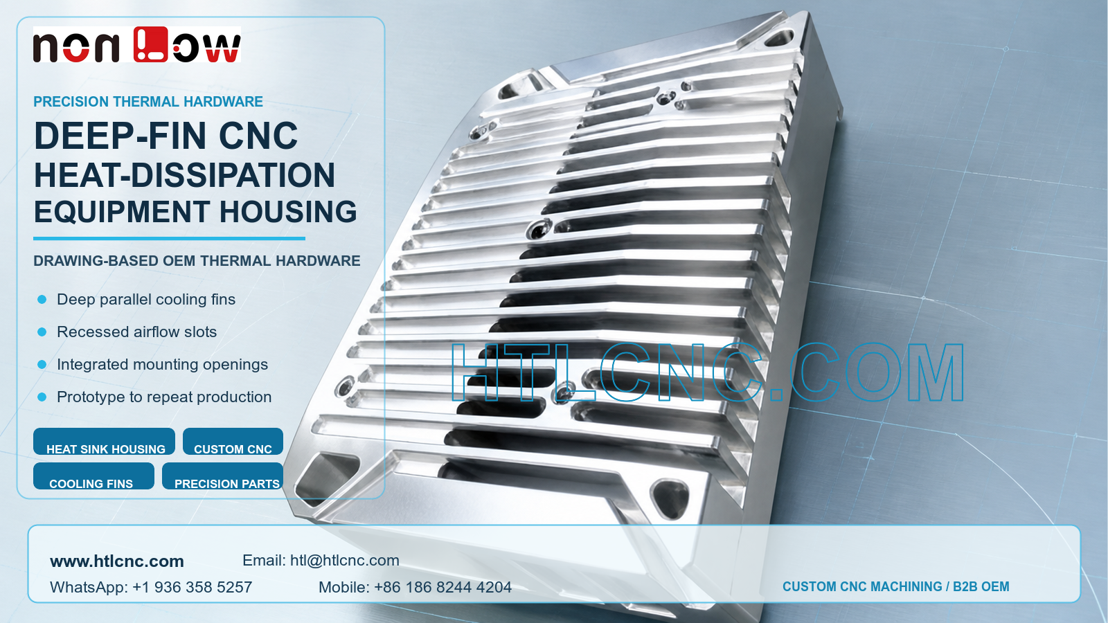
A deep-fin CNC heat-dissipation equipment housing combines machined cooling fins, recessed airflow slots and mounting openings in one drawing-based OEM component.
A deep-fin CNC heat-dissipation equipment housing is a machined metal component that combines an equipment enclosure, external cooling geometry and assembly interfaces in one body. The pictured part visibly includes many parallel fins, elongated recessed slots, corner mounting openings and a stepped perimeter. These features can support heat-transfer and airflow objectives, but actual thermal performance cannot be determined from appearance alone; it must be validated against the customer's operating conditions, material specification and thermal test plan. HTL CNC provides drawing-based custom CNC machining for overseas equipment manufacturers, engineering teams and procurement organizations that need CNC heat sink housings from prototype review through repeat OEM production.
What Buyers Can Confirm from the Visible Geometry
The most evident manufacturing feature is the dense field of parallel machined cooling fins. The face also contains long slots positioned between selected fin regions, several fastening or locating openings and a perimeter frame with changing levels. This combination means the part should not be reviewed as a decorative cover. Fin spacing, fin height, slot location, mounting relationships and the remaining wall beneath the fin field may all influence assembly or thermal behavior.
The RFQ should identify the functional mounting face, the surfaces that contact heat-generating hardware, the intended airflow direction and any areas that must remain free of coating. Material grade, flatness, surface roughness and critical position controls should come from the released drawing and STEP file. A supplier should not infer these requirements from a photograph.
Machining Deep Parallel Cooling Fins
Closely spaced fins create a different process challenge from a simple pocket or plate. Tool diameter, reach, chip evacuation and the stiffness of the remaining fins must be considered together. A practical route may retain supporting stock during roughing, remove material in balanced stages and finish the fin channels only after the main body has reached a stable condition. Exact operations depend on the released geometry and material.
The drawing should define fin thickness, pitch, height, root radius and permitted edge condition where these characteristics are functional. Deep channels also need a realistic internal radius that matches cutter access. If a near-sharp root is essential, the customer and supplier should review whether a special cutter, secondary process or design relief is appropriate. Deburring must remove loose edges without bending the fins or changing the airflow openings.
Recessed Airflow Slots and Mounting Openings
The elongated slots interrupt the fin pattern and create localized changes in tool access and remaining section thickness. Their function may involve airflow, cable passage, fastening access or another assembly requirement; the final purpose must be confirmed by the buyer. Slot width, end radius, depth and position should therefore be controlled relative to the same datums used for the mounting interfaces.
Corner and face openings may require drilling, interpolation, countersinking, boring or thread machining according to the drawing. A 3-axis CNC machining route with qualified refixturing may suit some versions. Indexed 4-axis or 5-axis CNC machining can be evaluated when side access or cross-face relationships justify fewer setups. Machine-axis selection is an engineering decision based on access, tolerance, rigidity and volume rather than a marketing label.
Datum Planning for a Finned Equipment Enclosure
A stable datum plan connects the thermal face, fin field and mounting pattern. The process should establish reliable locating surfaces before extensive stock removal changes part stiffness. If the opposite side contains a device-contact surface, pocket or sealing interface, its relationship to the external fin field may be more important than the cosmetic appearance of individual tool paths.
For prototype work, flexible workholding can reduce setup preparation. For repeat OEM production, dedicated soft jaws or fixtures may improve loading consistency and protect finished fin edges. Clamping force must be applied to supported regions rather than thin walls or delicate fins. Revision-controlled setup documentation helps prevent an approved prototype route from drifting during later batches.
Inspection Should Follow Assembly and Thermal Function
Inspection can include overall profile, datum-face flatness, fin pitch and height, slot size and position, mounting-hole location, counterbore or thread characteristics, perpendicular relationships and drawing-defined geometric tolerances. Appropriate equipment may include calipers, micrometers, depth gauges, pin gauges, thread gauges, height measurement, optical inspection and CMM measurement depending on access and tolerance.
Overseas buyers can request selected dimensional results, a first-article inspection report or lot-level records for critical characteristics. The inspection scope, sampling plan, report format and retention period should be agreed during quotation. Visual checks should also cover bent fins, burrs in slots, contact marks, trapped chips and damage to protected mating surfaces.
Surface Treatment Requires Released Material Data
The housing may be supplied as machined or with a customer-specified surface treatment compatible with the confirmed material. Options may include anodizing, conversion treatment, plating, passivation, blasting, brushing, polishing, painting or another controlled finish, but no specific process should be selected from the image alone. Coating thickness, masked contact faces, plugged threads, color limits and cosmetic criteria should be included in the drawing or finish specification.
Fin channels and recessed slots require particular cleaning and handling attention. Packaging should prevent fin-to-fin contact, rubbing and impact during export. Separators, protective wrapping or formed trays can be considered according to size and shipment method. Labels should preserve part number, drawing revision, quantity and lot identity for receiving inspection.
Prototype Validation Before Low-Volume and Repeat Production
The prototype stage should verify more than dimensions. The customer should test mounting fit, fastener access, interface contact, airflow clearance, thermal behavior under actual operating load, finish compatibility and packaging protection. Any design change resulting from those tests should be released under a new revision before low-volume production begins.
After approval, controlled CNC programs, qualified workholding, defined inspection points and formal version control support repeat-order consistency. Expected batch size, annual demand, delivery schedule and destination allow HTL CNC to evaluate fixture investment, machine capacity, finishing lots, inspection workload and export packaging. Drawing confidentiality and controlled-file access can be addressed during supplier onboarding.
RFQ Information for Engineering Review
Send the released 2D drawing and STEP file together with material specification, prototype and production quantities, annual demand, critical dimensions, thermal-interface requirements, surface finish, inspection-document needs, packaging expectations, delivery schedule and destination. If thermal performance is a project requirement, include the operating environment, heat source, airflow condition and acceptance method so the manufactured geometry can be reviewed against real test criteria. HTL CNC can then prepare a process and quality review for the actual precision equipment enclosure rather than relying on generic assumptions.
Website: www.htlcnc.com Email: htl@htlcnc.com WhatsApp: +1 936 358 5257 Mobile: +86 186 8244 4204
Have a part ready for engineering review?
Send your drawing, STEP file, material and quantity directly to HTL CNC for a manufacturing quotation.