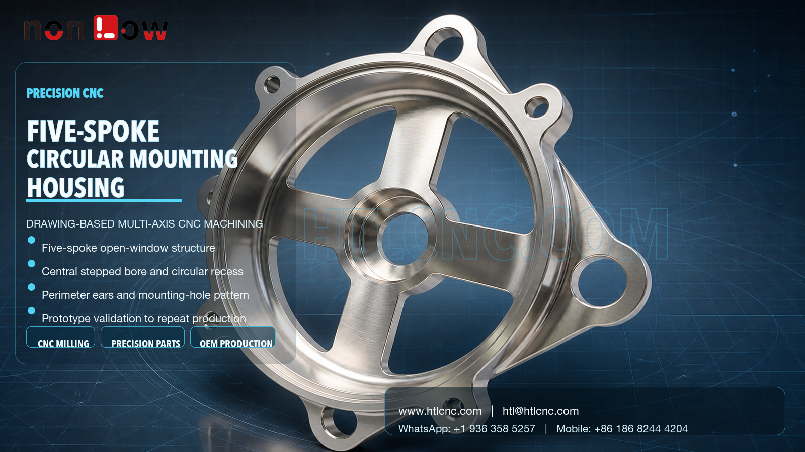
Five-spoke circular mounting housing CNC machining coordinates a central stepped bore, annular recess, open windows and perimeter mounting ears for prototype and repeat OEM production.
Five-spoke circular mounting housing CNC machining combines a central stepped bore, a broad annular recess, five open windows and multiple perimeter mounting ears in one integrated component. Those visible features create a drawing-based manufacturing challenge: the bore, circular seat, spoke structure and ear-hole pattern must be controlled as one functional geometry rather than inspected as unrelated dimensions. HTL CNC supports overseas OEMs, equipment builders and engineering teams with custom CNC machining, precision CNC parts, multi-axis CNC machining, prototype validation, low-volume production and repeat OEM manufacturing. The image does not establish the material grade, tolerance values or final application; those requirements must come from the customer's released drawings and STEP model.
What Is a Five-Spoke Circular Mounting Housing?
This product category is a circular machined support or housing with an open spoke structure linking a central hub to an outer ring. The pictured part visibly includes five spokes, five large windows, a central stepped bore, an annular recessed surface and several external mounting ears with different hole sizes. The design can reduce mass and create access through the windows, but the actual engineering purpose must be confirmed from the assembly.
For supplier qualification, buyers should provide the mating shaft, bearing, cover or installation geometry when those relationships affect the central bore, ring face or perimeter holes. Assembly information helps identify the true locating surfaces before fixture and inspection plans are frozen.
Central Bore and Annular Recess Control
The central hub and surrounding circular surfaces are likely to require a coordinated turning, boring or circular-milling strategy depending on stock form, size and drawing requirements. The released 2D drawing should define bore diameter, step depth, face relationship, edge condition and any fit or geometric tolerance. No fit class or sealing function should be inferred from appearance.
Inspection may use bore gauges, micrometers, depth tools, height systems, roundness equipment or CMM probing according to the specified characteristics. If the bore establishes the assembly axis, the same datum strategy should govern the annular ring and relevant mounting features.
Open Windows, Spokes and Distortion Risk
Five large windows leave relatively narrow spoke sections between the hub and outer ring. Material removal can change stiffness during machining, so roughing sequence, stock allowance, clamping pressure and finishing order should be reviewed before production. Balanced cutting and controlled re-clamping can help avoid transferring fixture stress into the finished geometry.
The window edges also require deliberate deburring. Loose burrs must be removed without rounding controlled transitions, thinning the spokes or altering a cosmetic edge standard.
Perimeter Ears and Mounting-Hole Relationships
The outer profile includes several mounting ears and a mixed hole pattern. These holes may not all serve the same function, so the drawing should distinguish locating holes, clearance holes and threaded features. Position, angular spacing and relationship to the central axis can be more important than each diameter alone.
Indexed 4-axis or 5-axis CNC machining may reduce datum transfers when access and tolerances justify it. A qualified 3-axis process with controlled fixtures can also be appropriate. Axis count is selected from geometry, tolerance, quantity and cost; it is not a quality claim by itself.
Process Planning from Prototype to Repeat Production
Prototype machining should prove the datum structure, clamping method, bore-to-ear relationship and surface-finish allowance. First-article inspection and assembly trials can reveal whether the released drawing fully describes the functional relationships. Corrections should be issued through controlled drawing and STEP revisions before low-volume ramp-up.
For repeat orders, qualified fixtures, locked programs, first-piece checks, tool-life controls and revision management support consistency. HTL's prototype and low-volume CNC machining service provides a staged route from sample verification to recurring supply.
Inspection Documentation for B2B Procurement
A risk-based inspection plan may cover the central bore and steps, annular face, spoke thickness, window profile, outer-ring geometry, ear-hole position and drawing-defined flatness, runout or position controls. Measurement methods and sampling levels should be agreed before quotation.
Overseas OEM buyers may also request first-article data, lot inspection records, material documents, finishing records or traceability for selected characteristics. Report scope should match the part number, revision, purchase order and agreed control plan.
Surface Finish and Export Handling
The visible image does not confirm a final treatment. Depending on the specified material and application, customers may request an as-machined finish, anodizing, plating, passivation, blasting, brushing, polishing, painting or another compatible process. Masked bores, coating allowance, cosmetic zones and protected edges must be identified on the drawing.
Open windows and projecting ears need packaging that prevents metal-to-metal contact and impact damage. Export packaging, labeling, destination and delivery schedule should be part of the sourcing review, especially for repeat releases or annual demand programs.
RFQ Information for Drawing-Based Manufacturing
Send the released 2D drawing and STEP file with material, prototype and production quantities, annual demand, functional datums, bore and ear-hole requirements, tolerances, finish, inspection-document needs, packaging and target delivery. HTL's custom CNC machining service can then prepare a process, quality and supply plan based on controlled requirements.
Website: www.htlcnc.com Email: htl@htlcnc.com WhatsApp: +1 936 358 5257 Mobile: +86 186 8244 4204
Have a part ready for engineering review?
Send your drawing, STEP file, material and quantity directly to HTL CNC for a manufacturing quotation.