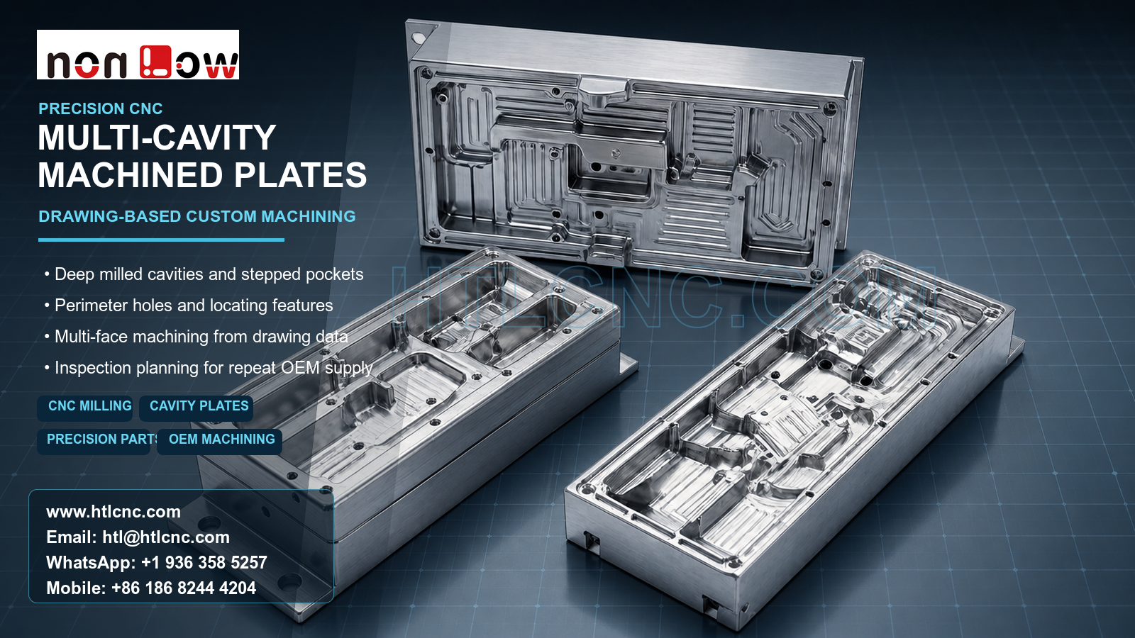
High-feature-density CNC milled base plates combine deep pockets, stepped floors, perimeter holes and local interfaces that require controlled datums, staged material removal and inspection planning.
High-feature-density CNC milled base plates are used when an OEM program needs broad structural components with many pockets, steps, holes, local interfaces and drawing-controlled relationships. The pictured set visibly contains three non-identical rectangular machined components: a tall rear plate with dense internal channels and two foreground blocks with deep multi-level cavities, perimeter holes and side features. HTL CNC supports overseas OEMs, product-development companies and equipment builders with custom CNC machining, precision CNC parts, multi-face CNC milling, prototype validation, low-volume production and repeat drawing-based manufacturing. The image does not establish material grade, tolerance, finish or final application; these requirements must come from the customer's released drawings and STEP data.
What Is a High-Feature-Density CNC Milled Base Plate?
A high-feature-density base plate concentrates different machining conditions in one component: large open pockets, narrow channels, stepped floors, local bosses, drilled or threaded features and several reference surfaces. Feature density matters because every operation changes the remaining stiffness and influences access for the next tool. A reliable process route therefore starts from functional datums and critical interfaces rather than simply machining the largest cavity first.
The three pictured components are not duplicate views of one part. An RFQ should identify each item with its own part number and revision, while the assembly model should show whether any faces, holes or cavities have a controlled relationship across the set.
How Should the Machining Sequence Be Selected?
Broad reference faces are normally established before deep internal geometry is finished. Bulk material can then be removed in stages while enough stock remains around walls, bosses and perimeter edges to support the part. Critical floors, bores and interface faces can be finished after the component has reached a more stable condition.
Tool diameter, projection, flute length, corner radius and chip evacuation should be reviewed against every cavity. Larger cutters can remove accessible stock efficiently, while smaller tools may be needed for residual corners and narrow transitions. An artificially small internal radius can increase cycle time and tool risk, so engineering review should confirm which radii are functional before quotation.
Datum Control Across Pockets, Holes and Side Features
The released drawing should define the primary mounting or seating surface, the secondary orientation reference and the feature that prevents rotational ambiguity. From this datum structure, pocket depth, hole position, local recesses and external interfaces can be related to one controlled coordinate system.
Some visible holes and openings are approached from faces other than the main cavity side. Depending on part size, tolerance relationships and quantity, the route may use controlled refixturing, indexed 4-axis work or 5-axis CNC machining. Axis count is not a quality claim by itself; the selected method must reduce access risk and preserve the drawing-defined relationships.
Managing Deep Pockets and Changing Part Stiffness
Deep pockets create long tool reach, interrupted engagement and limited chip clearance. As material is removed, thin walls and broad floors may respond differently to cutting force and clamping pressure. Balanced roughing, controlled finish allowance and suitable support can help limit distortion, but the plan must be based on the confirmed material, stock condition and tolerances.
The supplier should also review how the component is released from the fixture and measured in its free state. A part that appears flat while heavily clamped may move after removal, so drawing-defined flatness or profile requirements need an inspection method that reflects the agreed condition.
What Should Be Inspected on a Complex Base Plate?
A risk-based inspection plan may cover datum-face condition, overall profile, pocket and step depth, wall thickness, perimeter-hole position, bore size, thread acceptance, side-feature position and drawing-defined geometric controls. Measurement may combine calibrated hand tools, depth and bore gauges, height measurement, optical equipment and CMM probing according to access and tolerance.
For supplier qualification, the OEM can request first-article results linked to the part number, drawing revision and production lot. If the three components form one controlled set, the inspection scope should distinguish individual dimensions from assembly-level relationships. Material documents, finish records and any customer-required lot report should follow the same revision trail.
Surface Finish, Deburring and Export Protection
The bright metal appearance does not confirm a material or treatment. After material is specified, the buyer may request an appropriate finish such as anodizing, plating, passivation, blasting, polishing, painting or another process. Precision bores, threads, datum faces and coating-sensitive interfaces should be identified for masking or post-finish verification where applicable.
Complex cavities can retain chips or finishing media. Edge-break limits, cross-hole deburring, cleaning level and protective packaging should be agreed before production. Individual separation, protective covers or formed inserts may be appropriate when machined floors, cavity edges and locating surfaces must arrive without contact damage.
From Engineering Samples to Repeat OEM Supply
Prototype quantities allow the engineering team to confirm assembly fit, cavity access, fastener clearance, inspection strategy and finishing requirements. After approval, qualified fixtures, controlled CNC programs, first-piece inspection, tool-life monitoring and formal revision control support low-volume ramp-up and repeat production. HTL's custom CNC machining service provides drawing review and production planning, while prototype and low-volume CNC machining supports a staged route from sample validation to recurring supply.
RFQ Data for High-Feature-Density Base Plates
Send the released 2D drawing and STEP file for each component, plus an assembly model when relationships across the set matter. Include material, prototype quantity, production quantity or annual demand, datum scheme, critical pockets and holes, tolerances, surface finish, inspection-document scope, revision status, packaging, delivery destination and target schedule. HTL CNC can then review manufacturability, inspection coverage and the supply plan for the actual high-feature-density CNC milled base plates.
Website: www.htlcnc.com Email: htl@htlcnc.com WhatsApp: +1 936 358 5257 Mobile: +86 186 8244 4204
Have a part ready for engineering review?
Send your drawing, STEP file, material and quantity directly to HTL CNC for a manufacturing quotation.