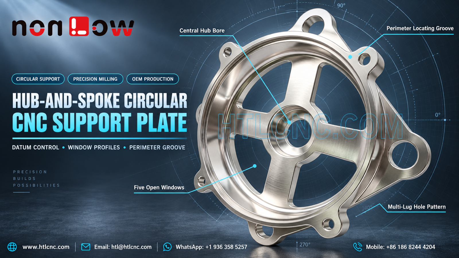
A hub-and-spoke circular CNC support plate combines a central hub bore, five open windows, a concentric perimeter groove and an irregular multi-lug hole pattern in one datum-controlled component.
A hub-and-spoke circular CNC support plate brings several feature families into one machined structure: a central stepped hub bore, five open windows, radial spokes, a broad annular face, a narrow perimeter groove and multiple external lugs with different hole sizes. The photograph does not establish the material grade, tolerance values, coating, bearing fit or final equipment. Those requirements must come from the buyer's released 2D drawing, STEP model and assembly data. HTL CNC supports overseas OEMs, product-development companies, equipment builders and procurement teams with drawing-based custom CNC machining, prototypes, low-volume ramp-up and repeat production.
Build the Supplier Control Plan Around One Axis
A circular support plate is easier to source when the RFQ states which bore, diameter or face establishes the functional axis. The central hub, annular face, perimeter groove and lug-hole pattern may all need to relate to that axis, but a supplier should not infer those relationships from the image. The drawing should define datums, basic dimensions and any runout, position, profile or flatness controls.
This shared datum framework is useful from quotation through inspection. HTL's custom CNC machining service reviews the released files and mating information before selecting workholding, cutting sequence and measurement methods.
Central Hub Bore Machining Sets the Reference
The visible center includes a stepped bore and surrounding hub face. The RFQ should define each diameter, depth, transition radius, edge break and surface requirement, together with any fit or coaxiality callout. If the bore locates a mating shaft or insert, the customer should provide the mating condition rather than expecting the machining supplier to choose a fit.
Depending on size, stock form and tolerance, the hub may be produced by boring, circular interpolation, turning or a combined route. Measurement may use calibrated bore gauges, micrometers, depth tools or CMM probing. The selected method should be agreed for the characteristic that controls assembly.
Perimeter Groove and Annular Face Need Separate Definitions
A narrow circular groove is visible near the outer ring, while the broader recessed face extends toward the spoke windows. The groove width, depth, diameter and edge radii should be dimensioned separately from the adjacent annular face. The image cannot confirm whether the groove is a locating, sealing, clearance or cosmetic feature.
If the groove is function-critical, the drawing should state its relationship to the central datum axis and whether dimensions apply before or after finishing. A supplier can then choose a tool path that controls circularity and depth without damaging the nearby rim.
Five Window Profiles Affect Spoke Balance
Five open windows leave five radial spokes between the central hub and outer ring. Window shape, corner radii, spoke width and blend transitions should be controlled as a coordinated profile rather than as disconnected linear dimensions. Uneven stock removal or excessive clamping force can shift the ring or hub after release.
A practical machining route may establish stable faces, rough the windows while support remains, allow stress to redistribute, and then finish the datum-related profiles. The sequence depends on material behavior, starting stock, part thickness, tolerance and quantity. Deburring should remove sharp edges without thinning a spoke or changing a controlled window profile.
Map Every Lug Hole from the Central Coordinate System
The outer silhouette includes several mounting lugs with visibly different hole sizes. The drawing should identify each lug and hole, state whether it is a locating hole, clearance hole or threaded feature, and define its radial and angular position from the selected coordinate system. Mixed hole sizes should not be treated as one repeated pattern.
A hole can meet its diameter requirement while the complete multi-lug hole pattern is rotated or shifted relative to the hub. Inspection therefore needs both feature-size checks and coordinate-position results. A numbered feature map helps engineering and procurement teams trace each reported value to the released revision.
Choose Milling, Turning or Indexed Access from the Full Model
The visible face may suit controlled CNC milling, while the concentric bore, recess and groove may benefit from turning or circular milling. Backside geometry, side features or restricted cutter access not visible in the photograph can change the machine and fixture plan.
Indexed 4-axis work or 5-axis CNC machining can reduce datum transfers when access and tolerance justify it. A qualified 3-axis process with purpose-built fixtures may also be appropriate. Machine-axis count follows the complete model, production quantity and inspection plan; it is not a quality claim by itself.
Prototype Validation Should Include Mating Geometry
A prototype should verify more than individual dimensions. The OEM team can check hub engagement, annular-face contact, groove clearance, window access, lug-hole alignment, fastener reach and assembly orientation with actual mating parts or approved gauges. Any change should update both the drawing and STEP file under a controlled revision.
HTL's prototype and low-volume CNC machining service supports engineering samples before recurring releases. Drawing confidentiality, approved-file control and obsolete-revision quarantine can be included in the supplier-qualification discussion.
Inspection Records for Repeat OEM Supply
A risk-ranked first-article report may cover overall thickness, central bore and steps, hub-face position, annular recess, perimeter groove, window profiles, spoke widths, outer-ring geometry, individual lug holes and drawing-defined geometric controls. Measurement may combine bore and depth tools, height systems, pin gauges, optical systems and CMM equipment.
For repeat production, qualified fixtures, locked programs, first-piece approval, tool-life rules and revision-specific inspection plans help preserve the accepted geometry. The RFQ should state the required report format, sampling level, traceability and any material or finishing documents before quotation.
Finish Allowance and Export Packaging
The bright metal appearance does not prove aluminum, stainless steel, plating, passivation, polishing or another treatment. Buyers should specify the exact material standard and condition, finish process, coating allowance, masking zones, cosmetic criteria and certificate scope. Close-fit bores, grooves and locating faces may require masking or post-finish verification.
Projecting lugs, narrow spokes and finished circular faces should be protected from impact and metal-to-metal contact. Export packaging may use separators, sleeves, edge protection or formed trays selected from the actual geometry and finish. Labels should identify part number, revision, quantity and production lot.
RFQ Checklist for a Hub-and-Spoke Circular CNC Support Plate
Send the released 2D drawing and STEP file, mating geometry and assembly orientation, exact material, prototype and production quantities, annual demand, functional datum axis, central hub bore, perimeter groove, window and spoke profiles, numbered lug-hole pattern, tolerances, geometric controls, edge breaks, finish, inspection-document scope, packaging, destination and target schedule. HTL CNC can then prepare a controlled process and supply plan for the hub-and-spoke circular CNC support plate.
Website: www.htlcnc.com Email: htl@htlcnc.com WhatsApp: +1 936 358 5257 Mobile: +86 186 8244 4204
Have a part ready for engineering review?
Send your drawing, STEP file, material and quantity directly to HTL CNC for a manufacturing quotation.