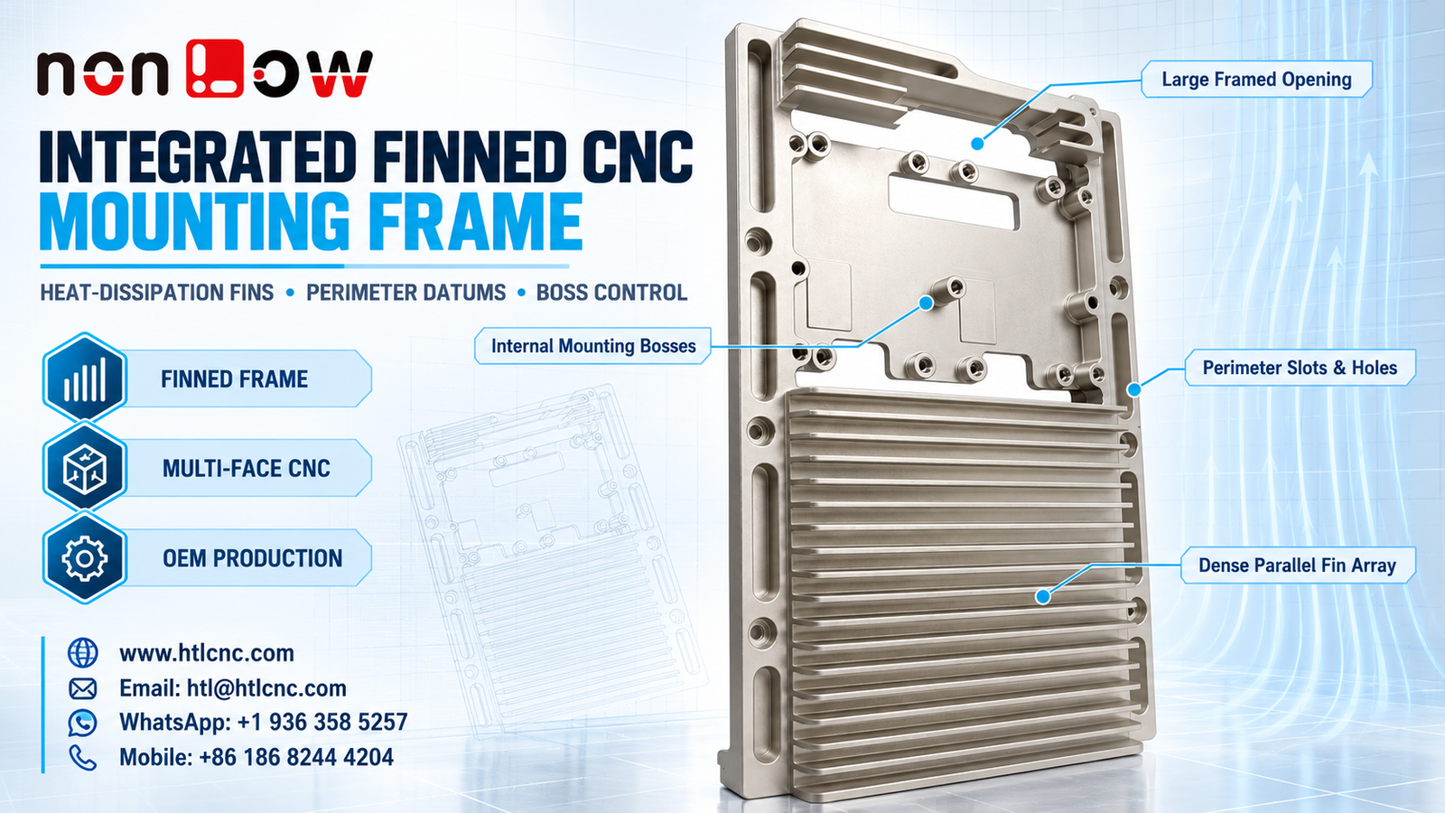
An integrated finned CNC mounting frame combines a dense parallel fin field, upper framed opening, internal mounting bosses and perimeter slots and holes in one tall machined structure.
An integrated finned CNC mounting frame places thermal-management geometry, assembly interfaces and a tall perimeter structure in one machined part. The visible component has a dense array of long parallel fins across its lower region, a large framed opening above, local upper ribs, a recessed internal mounting area with several bosses, and perimeter slots and circular holes. These visible features support a machining discussion, but the image does not establish material grade, dimensional tolerances, heat-transfer performance, finish or final application. Those requirements must come from the buyer's released 2D drawing, STEP model, assembly data and validation plan. HTL CNC supports overseas OEMs, equipment builders, product-development teams and procurement specialists with drawing-based custom CNC machining, prototypes, low-volume production and repeat supply.
Define the Functional Datum Structure First
A tall frame can contain many individually accurate features while still failing assembly if the mounting faces, boss pattern and perimeter holes are not related to one clear datum system. The drawing should identify the primary seating face, the secondary edge or centerline that controls orientation, and the feature used for clocking.
Baseline dimensions and geometric controls are generally clearer than long dimension chains across the complete height. HTL's custom CNC machining service reviews datum relationships before fixture design and setup sequencing.
Control the Parallel Fin Field Without Assuming Performance
The lower region visibly contains many long, closely spaced fins. The drawing should define fin pitch, height, thickness, root radius, straightness, end condition and any keep-out zones. The photograph alone cannot prove a cooling rating or airflow requirement; those values must be supplied and validated by the customer's engineering team.
Machining strategy must consider tool reach, chip evacuation and the changing stiffness of the base as the slots between fins are created. Balanced cutting, suitable cutter engagement and planned finishing passes can reduce deflection and protect fin spacing. Burr removal must not thin the fin edges or round a functional root geometry.
Protect Fin Roots During Deburring and Cleaning
Closely spaced fins can retain chips, coolant and loose burrs that are difficult to see from one direction. A process plan should define how the spaces are inspected and cleaned without bending an edge or contaminating a later coating process.
Where cleanliness is important, the buyer should specify residue limits, cleaning method, packaging condition and any particle-control standard. Visual access, controlled air or fluid cleaning, optical inspection and approved samples may form part of the acceptance method.
Number the Internal Mounting Bosses
The upper recessed area visibly includes multiple raised bosses or standoffs around a rectangular opening. Each boss should be numbered on the drawing and inspection report so its height, hole condition and position can be traced to the datum system.
Boss height can affect fastener seating and component stand-off distance. The RFQ should define whether holes are threaded, clearance, tapped after finishing or masked during coating. Counterbores, spotfaces, thread depth and perpendicularity must be specified rather than inferred from the image.
Relate the Large Framed Opening to the Mounting Zone
The upper opening and local ribs create an interrupted frame. Its width, height, corner radii, profile and edge distance may affect clearance or structural behavior, but the function cannot be confirmed visually. The released drawing should state which edges are functional and which are simply clearance geometry.
Removing the opening can release residual stress and alter frame flatness. A practical route may rough major open areas while the stock is rigid, alternate material removal, allow stabilization and reserve a controlled finish pass for the datum face and critical boundaries.
Separate Perimeter Slots, Holes and Reference Features
Repeated elongated slots and circular holes are visible around the perimeter. They should be classified as locating, fastening, clearance, ventilation or noncritical features only according to the design specification. Each category may need a different tolerance and inspection method.
For assembly-critical patterns, the report should capture true position, spacing, edge distance and perpendicularity relative to the frame datums. Pin gauges, height systems, optical equipment, CMM inspection or a customer-approved mating fixture may be used according to tolerance and access.
Manage Flatness and Twist Across the Tall Envelope
A high length-to-width frame with extensive material removal can move during roughing, release and finishing. The inspection plan should define how the part is supported and whether flatness or profile is measured in a free state or an agreed restrained condition.
Workholding should distribute support without forcing the frame into a temporary shape. Qualified fixtures, low-stress clamping, balanced stock removal and staged inspection can help distinguish machining error from measurement variation caused by support location.
Plan Multi-Face Access and Datum Transfer
The fin slots, upper recess, boss holes, perimeter openings and opposite-side features may require several tool directions. A controlled 3-axis route, indexed 4-axis process or 5-axis CNC machining may be selected from the complete model, tolerance and quantity.
The goal is to preserve functional relationships with rigid support and minimal uncertain refixturing. Machine axis count should follow access and datum risk rather than marketing preference. Soft jaws or a dedicated nest may protect finished fins and locate the established reference surfaces during secondary operations.
Confirm Material, Finish and Masking from the Specification
The bright metallic appearance does not prove aluminum, stainless steel, plating, passivation or another material or treatment. The RFQ should provide the exact material standard and condition, heat treatment, surface finish, coating thickness, masking zones, cosmetic criteria and certificate scope.
Fin edges, datum faces, boss tops, threaded holes and close-fit openings may need specific masking or post-finish inspection. If thermal contact is important, the customer should define the required interface finish and approved coating condition instead of relying on a general cosmetic note.
Prototype Validation and Repeat Production
Prototype quantities allow the engineering team to verify mounting alignment, boss seating, fastener access, perimeter-hole fit, fin clearance and the agreed support condition for inspection. Any change should update both the 2D drawing and STEP model under one controlled revision.
HTL's prototype and low-volume CNC machining service supports samples and pilot builds before recurring production. After approval, qualified programs, controlled fixtures, first-piece checks, tool-life rules and revision control can support stable repeat supply.
Inspection, Packaging and RFQ Checklist
A risk-based first-article plan may cover overall profile, datum flatness, frame twist, fin pitch and height, upper-opening profile, boss height and hole position, perimeter slot geometry, mounting-hole position and drawing-defined geometric controls. Reports should identify part number, revision, lot and measurement method.
Packaging should prevent fin edges and frame corners from carrying shipping load. Formed trays, rigid separators or individual sleeves may be needed according to geometry and finish. Send the released 2D drawing, STEP file, mating-part information, exact material, prototype and production quantities, annual demand, functional datums, fin requirements, boss and hole details, opening and perimeter geometry, tolerances, finish, cleanliness, inspection-document scope, packaging, destination and schedule. HTL CNC can then prepare a controlled machining and quality plan for the integrated finned CNC mounting frame.
Website: www.htlcnc.com Email: htl@htlcnc.com WhatsApp: +1 936 358 5257 Mobile: +86 186 8244 4204
Have a part ready for engineering review?
Send your drawing, STEP file, material and quantity directly to HTL CNC for a manufacturing quotation.