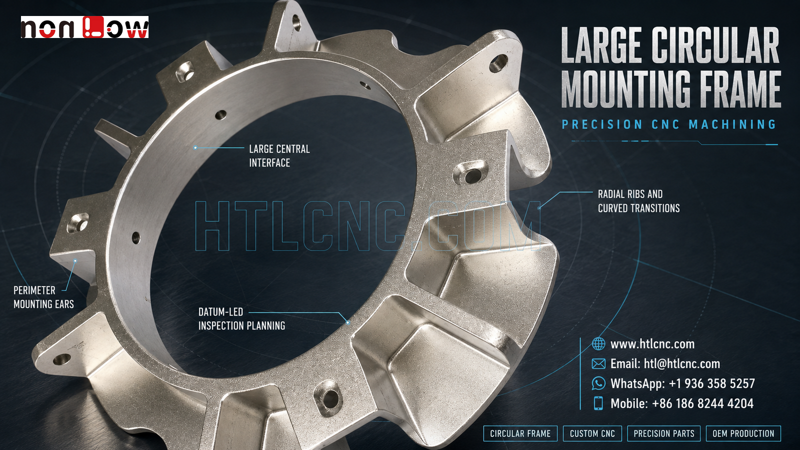
Large circular mounting frame CNC machining coordinates an annular interface, radial stiffening ribs and perimeter lug holes through a controlled datum and inspection plan.
Large circular mounting frame CNC machining is required when an OEM structural part combines a broad annular interface, a large central opening, radial stiffening features and mounting lugs around the perimeter. The pictured single frame visibly includes a machined inner circular face, multiple projecting ears with holes, curved rib transitions and locally raised mounting regions. HTL CNC supports equipment builders, product-development companies, contract manufacturers, engineers and procurement teams with custom CNC machining, precision CNC parts, large-format CNC milling, prototype validation, low-volume production and repeat drawing-based OEM manufacturing. The image does not confirm material, stock form, tolerance, load rating, surface treatment or final application; those requirements must be defined by the customer's released 2D drawing, STEP model and assembly specification.
What Is Different About an Annular Support Frame?
Unlike a solid plate, an annular frame concentrates material around a large opening and transfers geometry through a ring, ribs and local mounting ears. The sourcing challenge is therefore not only overall diameter. Buyers need to define which circular surface locates the assembly, which face establishes axial position and which perimeter holes provide location rather than clearance.
A mating-part model or interface drawing helps the supplier understand the real datum chain. It also prevents a general outside profile from receiving unnecessary controls while a critical ring face or lug position is left ambiguous.
Large Circular Interface and Datum Strategy
The visible inner circular surface provides the most obvious candidate for a functional interface, but its role cannot be assumed. The drawing should state diameter, axial depth, face condition, edge requirement and any relationship to a selected datum axis only where the assembly requires it. If a separate face establishes installation, that face should lead the process and inspection plan.
Depending on part size, stock condition and tolerance, the circular feature may be produced by boring, circular interpolation, contour milling or a qualified combination. A stable datum should remain available while roughing and finishing proceed so the ring geometry and perimeter features can be related to the same controlled reference.
Radial Ribs and Curved Transitions
The outer structure contains several ribs and curved blends connecting the annular body to thicker local sections. These features can change stiffness as material is removed. Roughing sequence, residual stock, cutter engagement and clamping force should therefore be reviewed before critical circular and lug features are finished.
Curved transitions also create varying tool contact and access. Tool paths should maintain controlled engagement without overworking local corners. Deburring must remove loose edges while preserving drawing-defined radii, rib thickness and functional transitions.
Perimeter Mounting Ears and Mixed Hole Directions
The projecting ears are distributed around the frame and appear at different elevations or orientations. The drawing should distinguish threaded, clearance, counterbored and locating holes, and should define angular or positional relationships to the annular datum where required. A mixed hole pattern can pass individual diameter checks and still fail assembly if the pattern is not controlled from the correct reference.
Qualified refixturing, indexed 4-axis work or 5-axis CNC machining may be evaluated according to access, tolerance and quantity. The best route is the one that reduces unnecessary datum transfer while maintaining rigid support and inspection access; axis count by itself is not a quality claim.
Workholding a Large Open Structure
A large central opening limits the areas available for clamping. Fixture contacts should support rigid regions, avoid finished interfaces and distribute force so the ring is not temporarily distorted. If the frame is flexible in its free state, inspection after unclamping may be needed to confirm the actual delivered geometry.
For prototype quantities, modular fixtures may provide enough access for engineering review. Recurring production can justify qualified soft supports or dedicated fixtures that improve loading consistency and protect finished surfaces. HTL's custom CNC machining service reviews geometry, stock, quantity, datum structure and inspection scope before selecting the process route.
Inspection Evidence for OEM Supplier Qualification
A risk-based inspection plan may cover the annular diameter and face, ring profile, lug-hole position, angular spacing, rib-related surfaces, overall envelope and drawing-defined flatness, runout, position or profile controls. Measurement may combine large-capacity gauges, height systems, pin and thread gauges, optical equipment, rotary methods, fixtures and CMM probing according to size and tolerance.
First-article records should identify the part number, drawing revision, material lot when required and measurement condition. Overseas buyers should agree whether reports need full dimensional results, selected critical characteristics, material records, finishing records or traceability. The evidence package should follow the purchase order and approved revision.
Finish and Export Packaging for Projecting Features
The bright textured appearance does not prove a material or finishing route. After material and service environment are specified, possible options may include an as-machined condition, blasting, polishing, plating, passivation, anodizing, painting or another compatible process. Critical ring faces, holes and threads affected by coating thickness should be identified for masking, allowance or post-finish verification.
Projecting ears and thin outer features are vulnerable to impact during transport. Export packaging may require individual separation, formed supports, protective covers and orientation control so the annular face and lug edges do not contact adjacent parts or the outer carton.
Prototype Validation and Repeat OEM Production
A prototype should be checked with the intended mating geometry wherever possible. The engineering team can verify ring fit, axial seating, lug alignment, fastener access, clearances and the proposed measurement method. Load, vibration, sealing or life tests require customer-defined conditions and acceptance criteria; no such performance can be inferred from the photograph.
After approval, controlled CNC programs, qualified fixtures, first-piece checks, tool-life monitoring and revision control support repeat-order consistency. HTL's prototype and low-volume CNC machining provides a staged path from sample verification to recurring releases, delivery planning and annual-demand programs.
RFQ Checklist for a Large Circular Mounting Frame
Send the released 2D drawing, STEP file and relevant mating-part or assembly model. Include material, prototype and production quantities, annual demand, functional ring and face datums, lug-hole definitions, key tolerances, finish, inspection-document scope, cosmetic zones, packaging, destination and target schedule. HTL CNC can then review the actual large circular mounting frame CNC machining project and prepare a controlled manufacturing, quality and supply plan.
Website: www.htlcnc.com Email: htl@htlcnc.com WhatsApp: +1 936 358 5257 Mobile: +86 186 8244 4204
Have a part ready for engineering review?
Send your drawing, STEP file, material and quantity directly to HTL CNC for a manufacturing quotation.