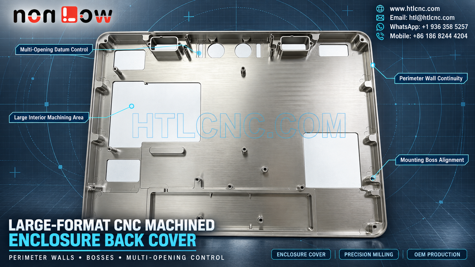
A large-format CNC machined enclosure back cover combines a broad interior floor, perimeter walls, multiple openings and mounting bosses that must remain connected to one functional datum system.
A large-format CNC machined enclosure back cover can consolidate a broad interior surface, continuous perimeter walls, multiple rectangular and circular openings, local recesses and mounting bosses into one structural component. The pictured part visibly includes a rounded rectangular outer frame, a large internal machining area, several perimeter cutouts, raised posts and bosses, and a long recessed region near one edge. The image does not establish the material grade, wall thickness, flatness tolerance, surface treatment, sealing function or final equipment application. Those requirements must come from the buyer's released 2D drawing, STEP model and assembly specification. HTL CNC supports overseas OEMs, product-development teams, equipment builders and procurement groups with drawing-based custom CNC machining, prototype enclosure parts, low-volume ramp-up and repeat production.
Why Large Enclosure Covers Need Early Process Review
Part size changes the manufacturing risk even when individual features appear simple. A broad cover can respond to stock stress, uneven material removal, clamp pressure and temperature across a larger span. The RFQ should identify the functional seating face, critical wall heights, flatness zones, cosmetic areas and any surfaces that interface with a frame, gasket or internal module.
A complete STEP model helps the supplier review tool travel, fixture access and deep-wall clearance. The released 2D drawing should remain the authority for datums, tolerances and acceptance criteria. HTL's custom CNC machining service uses both files to select stock, workholding, cutting sequence and inspection methods.
Broad Interior Machining and Flatness Strategy
The large interior floor occupies most of the visible part. Its final thickness, flatness and surface condition cannot be confirmed from the photograph. If the floor supports electronics, shielding, thermal interfaces or another customer-defined assembly, the drawing should identify the functional zones and distinguish them from ordinary clearance surfaces.
A suitable route may use balanced roughing, controlled stock allowance, intermediate stress-relief time or refixturing before final facing. The actual plan depends on material, starting form, removed volume, tolerance and quantity. Flatness should be checked after unclamping when clamp force could mask part movement.
Perimeter Wall Continuity and Edge Relationships
The visible perimeter wall follows the rounded rectangular outline and includes local interruptions, ledges and corner features. The buyer should define wall height, thickness, profile, corner radii and the relationship between the wall and the main seating face. If a seal, bezel or mating enclosure contacts the perimeter, the controlled interface should be marked clearly.
Long cutters and deep wall access can affect deflection and surface consistency. Tool selection should balance reach, rigidity and corner access. Where the wall contains local notches or transitions, deburring must preserve the specified edge and avoid damaging adjacent cosmetic surfaces.
Multiple Openings Need Functional Grouping
The back cover contains rectangular openings of different sizes, two central circular openings and other local cutouts. Their functions cannot be inferred from the image, so the RFQ should group them by the mating component or assembly interface they support. Each group may need its own locating reference while remaining connected to the cover's primary datum system.
The drawing should define opening size, corner radii, position, edge break and any backside step or recess. If several openings are revised during product development, feature IDs in the inspection report and CAD model reduce ambiguity. Controlled 3-axis milling may be sufficient for accessible features; side details or restricted access can justify indexed 4-axis or 5-axis CNC machining after the full model is reviewed.
Mounting Boss Alignment Across a Large Span
Raised bosses and posts are distributed around the interior and perimeter. Their diameter, height, thread, bore, counterbore and function are not visible with enough certainty to specify. The 2D drawing should state which bosses locate internal assemblies, which accept fasteners and which are clearance or support features.
Boss height and position should normally be measured from the same functional references used by the mating assembly. Checking each boss from a nearby raw wall may produce locally acceptable results without proving that all mounting points lie in the correct plane or coordinate system. Thin posts may also need cutting and deburring methods that avoid bending or thread damage.
Workholding Without Distorting the Cover
Fixtures for a large cover should support rigid regions and distribute force without blocking critical features. The process engineer should review where clamps contact, how the part is located after flipping and which surfaces must remain free of marks. Vacuum fixtures, soft jaws, dedicated plates or modular supports may be considered depending on actual geometry and material.
In-process checks can monitor reference faces, wall height and boss position before too much material is removed. If the part requires machining on both faces, the transfer datum and requalification method should be documented rather than relying on the unfinished outer profile.
Material and Finish Must Be Specified
The bright brushed appearance does not prove aluminum, stainless steel, plating, anodizing, passivation or any other treatment. The RFQ must state the exact material standard and condition, allowed substitutions, finish process, cosmetic reference, masking zones, dimensional allowance and certification scope. HTL will not infer material or treatment from reflectivity.
Threads, boss faces, seating surfaces and gasket regions may require masking or post-finish verification. The drawing should state whether dimensions apply before or after finishing. Where appearance matters, approved limit samples and defined viewing conditions can reduce subjective acceptance disputes.
Inspection Planning for a Large Machined Cover
A risk-based plan may cover overall envelope, outside profile, floor thickness and flatness, perimeter wall height and profile, opening dimensions and positions, boss height and location, threads, recessed regions and drawing-defined geometric controls. Measurement may combine calibrated hand tools, height systems, thread gauges, optical equipment, surface plates and CMM inspection according to feature access and tolerance.
The inspection fixture must reproduce the drawing datum scheme without forcing the cover into shape. First-article records should identify part number, revision, production lot, material lot when required and the equipment used. For repeat orders, trend data on broad-face flatness and key boss relationships can reveal process drift earlier than final assembly.
Prototype Qualification Before Low-Volume Ramp-Up
Prototype parts allow the OEM team to check seating, internal-module alignment, opening clearance, fastener access, wall interfaces, cable or connector paths and cosmetic condition with actual mating assemblies. Any change to bosses, cutouts, wall geometry or finish should update the 2D drawing and STEP model together under formal revision control.
HTL's prototype and low-volume CNC machining service supports engineering samples before recurring production. After approval, qualified fixtures, controlled programs, first-piece verification and revision-specific inspection plans help maintain consistency across releases.
Packaging and Delivery for Large Covers
Large covers are vulnerable to corner impact, broad-face scratching and bending during handling. Packaging may use protective film, perimeter guards, separators, sleeves or formed trays selected from the actual dimensions and finish. Parts should not carry transport load through delicate bosses or narrow wall sections.
Labels should show part number, revision, quantity and production lot. Annual demand, order cadence, destination and delivery windows help the supplier plan stock, machine capacity, outside finishing, inspection and export packaging. Supplier qualification should also cover drawing confidentiality, obsolete-revision quarantine and corrective-action records.
RFQ Checklist for a Large-Format CNC Machined Enclosure Back Cover
Send the released 2D drawing and STEP file, assembly orientation and mating models, exact material, prototype and production quantities, annual demand, functional datums, floor and wall requirements, opening definitions, boss and thread details, tolerances, edge breaks, finish and cosmetic zones, inspection-document scope, packaging, destination and delivery schedule. HTL CNC can then review the large-format CNC machined enclosure back cover and propose a controlled machining, inspection and repeat-supply plan.
Website: www.htlcnc.com Email: htl@htlcnc.com WhatsApp: +1 936 358 5257 Mobile: +86 186 8244 4204
Have a part ready for engineering review?
Send your drawing, STEP file, material and quantity directly to HTL CNC for a manufacturing quotation.