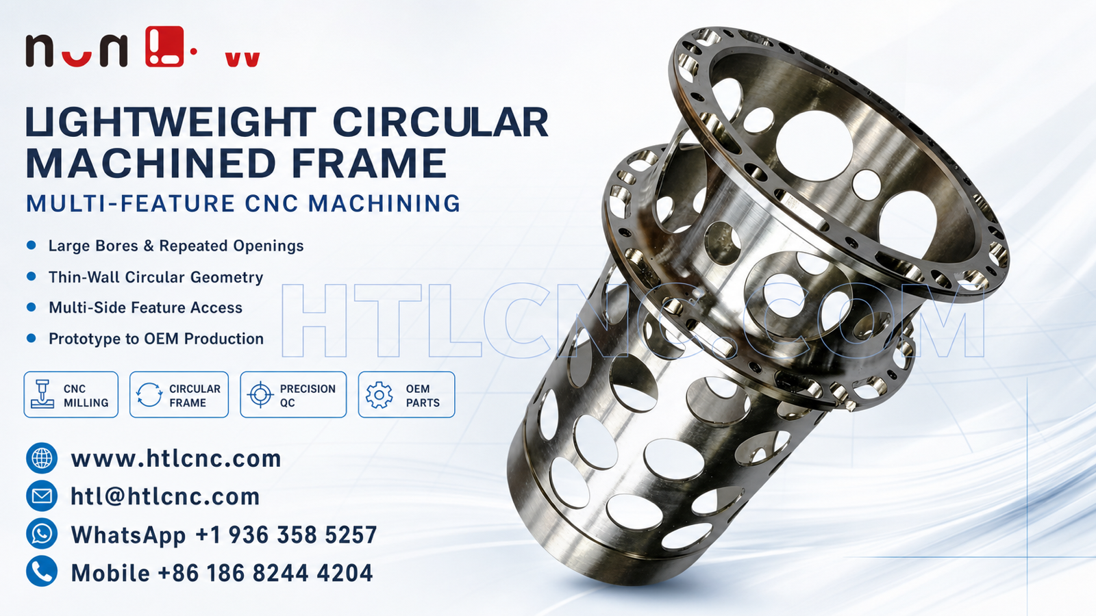
Drawing-based CNC machining for lightweight circular frames with repeated openings, large bores, thin-wall geometry and multi-side features from prototype to OEM production.
Lightweight circular frames can combine large open areas with repeated mounting features, close edge spacing and functional surfaces distributed around a cylindrical structure. The component shown here uses several connected circular sections, broad side openings, smaller holes around the rims and machined surfaces on multiple levels. These features reduce bulk while creating a part that requires careful support throughout machining.
HTL CNC manufactures custom circular frames, open structural components and multi-feature machined parts from customer drawings, STEP files and approved samples. We support engineering prototypes, low-volume validation and repeat OEM production. The exact material, dimensions, tolerances, finish and final use must always follow the customer's approved technical documents.
Large Bores and Repeated Openings
The visible component contains large circular openings through the side walls together with smaller repeated holes around the end rims. These openings can interrupt stiffness and leave narrow sections between adjacent features. Process planning should consider the order of material removal, tool engagement and the amount of support remaining at each stage.
Hole diameter alone does not define manufacturability. Position, spacing, edge distance, perpendicularity and the relationship between each opening and the selected datum structure may affect assembly. Drawing review should identify which bores, holes and rim faces are functionally critical so the machining and inspection plan can focus on the correct relationships.
Thin-Wall Circular Geometry and Stability
Open circular structures can become sensitive to clamping force as material is removed. Excessive fixture pressure may distort the component during machining, while insufficient support can allow vibration or movement. A controlled roughing and finishing sequence can help maintain stability without forcing the part away from its natural free-state geometry.
Toolpaths may be balanced around the circumference, leaving support where practical until later operations. Final passes should account for tool reach, interrupted cutting and the changing stiffness of the remaining walls. Edge breaks and deburring also require attention around every large opening and repeated rim hole.
Multi-Side Feature Access
Features around a circular frame may face several directions and may not be reachable from one setup. Depending on the approved drawing, the manufacturing route can use CNC milling with controlled reclamping, 4-axis indexing, 5-axis machining or a combination of turning and milling operations. The correct route depends on feature access, datum relationships, tolerance requirements, part size and production quantity.
Multi-axis access can reduce repeated setups and help maintain positional relationships between features on different sides. However, equipment choice should follow the actual geometry rather than the visual appearance alone. Fixture clearance, cutter length, chip evacuation, burr access and inspection access must be reviewed together before production is released.
Inspection and Surface-Finish Planning
Inspection can focus on rim dimensions, large bore sizes, repeated hole positions, circular face relationships, wall geometry and any drawing-defined runout, concentricity or flatness requirements. Depending on the agreed quality plan, verification may use calipers, micrometers, bore gauges, height measurement, dedicated gauges and CMM inspection.
The component may be supplied as machined or with a customer-specified surface treatment appropriate to the specified material. Blasting, anodizing, plating, passivation, polishing, painting or another approved process may be considered only when defined by the drawing. Coating allowance, masked areas, thread protection and cosmetic zones should be confirmed during quotation.
From Prototype Review to OEM Production
Prototype machining allows engineering teams to verify fit, stiffness, feature access, assembly relationships and inspection methods before repeat quantities are released. After approval, controlled programs, repeatable fixtures, revision management and documented inspection points support stable OEM manufacturing.
For an engineering review and RFQ, send your 2D drawing, STEP file, specified material, quantity, critical tolerances, inspection requirements and surface-finish notes.
Website: www.htlcnc.com Email: htl@htlcnc.com WhatsApp: +1 936 358 5257 Mobile: +86 186 8244 4204
Have a part ready for engineering review?
Send your drawing, STEP file, material and quantity directly to HTL CNC for a manufacturing quotation.