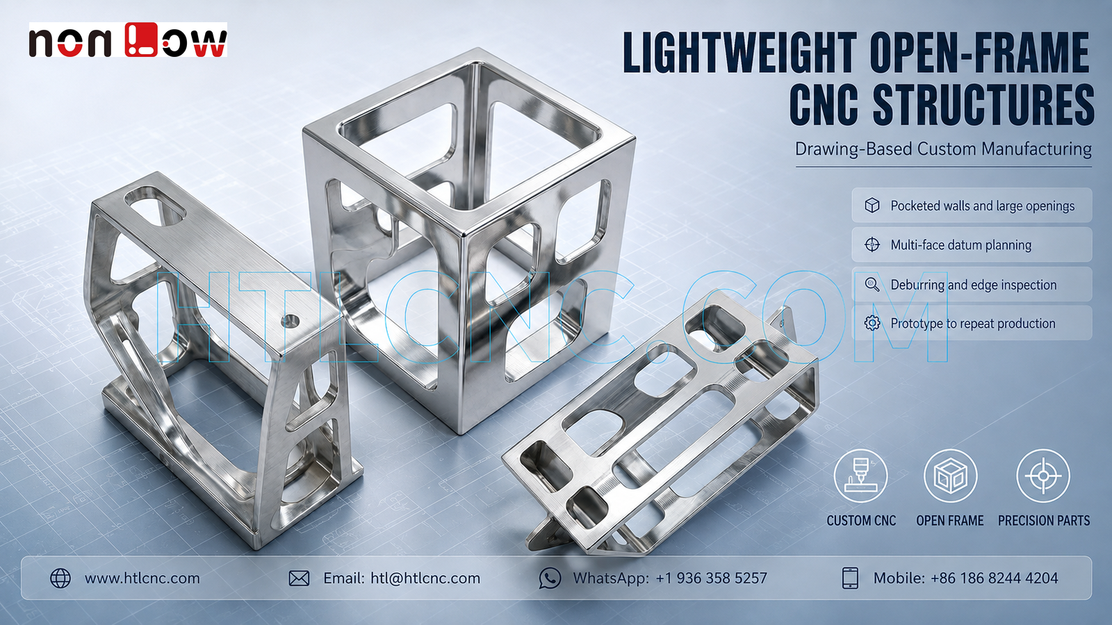
Lightweight CNC machined frame components require controlled datum planning, pocket and window machining, edge inspection and repeatable production across a related part family.
Lightweight CNC machined frame components help OEM engineering teams reduce unnecessary mass while retaining defined mounting faces, walls and connection paths. The pictured family visibly includes three open structures with large rectangular windows, narrow webs, machined faces and features approached from several directions. HTL CNC supports overseas equipment builders, product-development companies, contract manufacturers and procurement teams with custom CNC machining, precision CNC parts, multi-face milling, prototype validation, low-volume production and repeat drawing-based manufacturing. The photograph does not establish material grade, tolerance, load capacity, surface treatment or end use; those requirements must come from the customer's released 2D drawings, STEP models and assembly data.
What Defines a Lightweight Machined Frame Component?
A lightweight machined frame removes material from low-priority regions while preserving the interfaces and structural paths defined by the product engineer. Large windows, pocketed walls and connecting webs are visible here, but their function cannot be inferred from appearance alone. The drawing should distinguish datum faces, mounting locations, controlled wall thicknesses and clearance openings from purely cosmetic surfaces.
This distinction matters during supplier qualification. A shop should not apply the same tolerance to every edge, because doing so adds cost without necessarily improving assembly. A clear datum structure and feature classification allow machining and inspection effort to follow actual product risk.
Planning a Related Family of Different Frame Geometries
The three pictured components are not duplicates. One is a tall square frame, another has an arched side profile, and the third is a lower rectangular structure with multiple openings and a projecting tab. A family-production plan should preserve separate part numbers, revisions, programs and inspection records while identifying any shared tools, stock strategies or measurement methods.
For an OEM program, this is more useful than treating every component as an isolated quotation. Common manufacturing assumptions can be reviewed once, but critical dimensions and acceptance criteria must remain tied to each released drawing. Revision control should prevent a change to one member of the family from being applied automatically to another.
Pocketed Walls, Windows and Tool Access
Large openings reduce mass and improve access, but they also change workpiece stiffness as roughing progresses. The machining sequence should retain support around thin walls and webs until the main stock removal is complete. Controlled remaining stock, balanced roughing and suitable cutter reach can reduce local movement before final profiles are finished.
Window corners, internal radii and narrow transitions should be reviewed for tool access. Practical corner radii allow more rigid cutters and can improve consistency, while unnecessarily sharp internal corners may require smaller tools and longer cycles. Any radius with a functional purpose should be stated on the drawing rather than inferred by the supplier.
Multi-Face Datum Planning and Setup Control
Open frames commonly combine top faces, side windows, end interfaces, holes and local tabs. Depending on access, quantity and tolerance, the route may use qualified 3-axis refixturing, indexed 4-axis work or 5-axis CNC machining. The objective is to maintain relationships between features and reduce unnecessary datum transfer, not simply to maximize axis count.
Clamping should act on sufficiently rigid regions and avoid temporarily pulling an open structure out of shape. When a second setup is required, locating surfaces should remain protected and accessible. The inspection method must reference the same functional datum logic used by the released drawing.
Deburring and Edge Condition Across Open Structures
Each window creates additional edges and corner transitions. Deburring must remove loose material and sharp handling hazards without rounding a datum, thinning a web or changing a drawing-defined edge. Intersections and enclosed corners may require inspection from more than one viewing direction.
Customers should define edge-break limits, cosmetic zones and any surfaces that must remain sharp for location or sealing. Cleaning requirements also matter because open pockets and internal ledges can retain chips or finishing media if the process is not planned for complete removal.
Inspection Evidence for an OEM Part Family
A risk-based plan may cover datum-face condition, overall envelope, window position, web thickness, wall parallelism, local hole size and position, tab geometry, thread acceptance and drawing-defined profile or perpendicularity controls. Measurement can combine calibrated hand tools, height systems, optical inspection, CMM probing and customer-approved functional fixtures according to access and tolerance.
For supplier onboarding, the evidence package should identify part number, revision, production lot and measurement method. First-article reporting can be tailored to the critical characteristics of each frame. Repeat orders benefit from controlled programs, qualified setups, first-piece approval and documented reaction plans rather than a generic inspection statement.
Finishing and Protection of Thin Edges
The bright metal appearance does not confirm a material or finish. Once the customer specifies alloy and service environment, suitable options may include an as-machined condition, blasting, polishing, plating, passivation, anodizing, painting or another compatible process. Coating allowance, masking and post-finish inspection should be defined for close fits, holes, threads and datum surfaces.
Thin webs, projecting tabs and finished edges can be damaged in transit. Export packaging may need individual separation, formed supports and nonabrasive protection. Packaging orientation and labeling should keep different part numbers from being mixed during receiving and assembly.
From Prototype Review to Repeat Production
Prototype builds allow the OEM to check fit, mounting access, clearance through the windows, adjacent-component interference and the proposed inspection method. Structural, vibration, thermal or life validation requires customer-defined conditions and acceptance criteria; no performance claim can be made from the image.
After approval, HTL can support low-volume ramp-up and repeat production with controlled CNC programs, fixture qualification, revision management, first-piece checks and lot-level records. The custom CNC machining service supports manufacturability review, while prototype and low-volume CNC machining provides a staged path from engineering samples to recurring OEM releases.
RFQ Checklist for Lightweight Frame Components
Send the released 2D drawing and STEP file for every component, together with the assembly model when interface relationships matter. Include material, prototype quantity, production quantity or annual demand, functional datums, controlled wall and web dimensions, hole and thread definitions, tolerances, surface finish, inspection-document scope, revision status, packaging, delivery destination and target schedule. HTL CNC can then review the actual lightweight CNC machined frame components and prepare a manufacturing, quality and supply plan.
Website: www.htlcnc.com Email: htl@htlcnc.com WhatsApp: +1 936 358 5257 Mobile: +86 186 8244 4204
Have a part ready for engineering review?
Send your drawing, STEP file, material and quantity directly to HTL CNC for a manufacturing quotation.