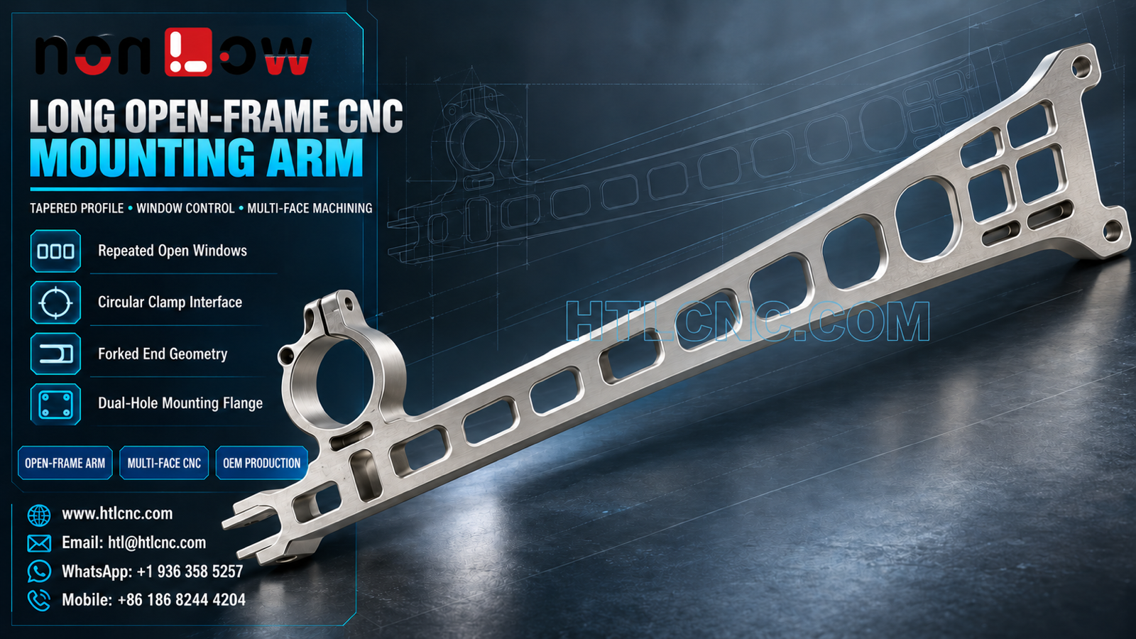
A long open-frame CNC mounting arm links a circular clamp interface, repeated windows, a tapered profile, forked end geometry and a two-hole mounting flange across one extended datum structure.
A long open-frame CNC mounting arm is difficult not because of one isolated feature, but because several distant interfaces must remain related across an extended, lightweight structure. The visible one-piece part has a tapered profile, repeated rectangular windows, a circular split-clamp feature near one end, a forked terminal, local slots and holes, and a broad two-hole mounting end. The source image shows two near-duplicate views of the same part; the poster uses only one selected view. The image does not establish material grade, tolerance, load rating, finish or final application. Those requirements must come from the buyer's released 2D drawing, STEP model and assembly information. HTL CNC supports overseas OEMs, product-development companies, equipment builders, engineers and procurement teams with drawing-based custom CNC machining, prototypes, low-volume production and repeat supply.
Start with the Two Functional Ends
The process plan should first identify what the forked end, circular clamp and broad mounting end do in the assembly. The drawing should define the primary seating plane, the axis of the circular interface and the holes or faces that control the arm's length and clocking.
A long component can meet local dimensions at each end while still creating assembly error between them. Baseline dimensions and datum-based geometric controls are usually clearer than a long chain of intermediate measurements. HTL's custom CNC machining service reviews these relationships before fixture design and setup sequencing.
Support the Tapered Body Without Clamping Distortion
The arm becomes wider toward one end and contains extensive open regions. Workholding should support the long profile without forcing it into a temporary shape. Excessive clamp pressure can create a flat-looking condition during machining that changes after release.
A practical route may establish reference faces while the stock is still rigid, rough windows in balanced stages and reserve controlled finishing passes for the long edges and mounting interfaces. Support locations must stay clear of cutting paths and approved cosmetic surfaces.
Keep Repeated Windows on a Controlled Pitch
The open windows vary in size along the tapered body. The drawing should identify which dimensions are functionally controlled: window width and height, spacing, web thickness, edge distance, corner radius or profile location. Applying tight tolerance to every opening may add cost without improving assembly.
As material is removed, the remaining webs can react to cutting force and heat. Balanced stock removal, practical cutter radii and stable tool engagement help protect the long edge and local rib thickness. Deburring must not enlarge windows or thin narrow webs.
Machine the Circular Clamp Interface as a Functional Axis
The circular opening includes a split or interrupted clamp-like form with nearby holes and a local slot. The image does not prove how it clamps or what it mates with. The RFQ should define bore diameter, roundness, width, split condition, screw-hole details and any relationship to the arm's main mounting plane.
Boring, circular interpolation or another approved method may be selected from size and tolerance. Inspection can use bore gauges, pin or ring masters, CMM probing or a customer-approved mating component. If the split changes bore condition during fastening, the customer should provide the specified assembly and test state.
Control the Forked End Geometry
The opposite end visibly includes two projecting prongs and internal clearances. The drawing should define fork width, gap, depth, parallelism, local hole or slot details, edge breaks and the reference from which its position is measured.
Long, narrow prongs can be sensitive to tool pressure and handling. Roughing and finishing should preserve support, while packaging should prevent the terminal features from being bent or struck during transport.
Relate the Two-Hole Mounting End to the Long Axis
The broad end contains two mounting holes on a curved or flared profile. Hole diameter alone is insufficient when assembly also depends on spacing, true position, perpendicularity, edge distance and relationship to the circular clamp axis.
A first-article report can link the two-hole pattern to the part's datum system and overall length. Pin gauges, height measurement, optical equipment, CMM inspection or a mating fixture may be selected according to tolerance and access.
Choose Multi-Face Machining by Access and Datum Risk
The circular interface, side details, windows, fork and end holes may require several tool directions. A qualified 3-axis process with controlled refixturing, indexed 4-axis work or 5-axis CNC machining may be evaluated from the complete model and quantity.
The objective is to reduce uncertain datum transfer while maintaining rigid support. A more complex machine is useful only when it improves access, preserves relationships or reduces handling for the actual drawing requirements.
Inspect Long-Range Relationships, Not Only Local Features
A risk-based inspection plan may include overall length, long-edge profile, datum flatness, clamp-bore size and position, repeated-window geometry, web thickness, fork condition, end-hole position and drawing-defined geometric controls. The plan should distinguish local feature acceptance from relationships measured across the complete arm.
Long components also require an agreed measurement support condition. Inspection results can change if the part is supported at different points or forced against a reference surface. The report should state the fixture or support method when flatness, profile or end-to-end alignment is critical.
Confirm Material and Finish from the Specification
The metallic appearance does not prove aluminum, stainless steel, plating, passivation or another material or treatment. The RFQ should provide the exact material standard and condition, heat treatment, finish, coating thickness, masking zones, cosmetic criteria and certificate scope.
Close-fit bores, mounting holes and datum faces may require masking, allowance or post-finish inspection. If the long brushed surface is cosmetic, the buyer should define grain direction, acceptable handling marks and protected packaging.
Prototype Validation Before Repeat Supply
Prototype quantities allow engineering teams to verify clamp fit, fork clearance, mounting-hole alignment, fastener access, end-to-end geometry and the inspection support method with actual mating components. Any design change should update both the 2D drawing and STEP model under one revision.
HTL's prototype and low-volume CNC machining service supports engineering samples and pilot builds. After approval, controlled programs, qualified fixtures, first-piece checks, tool-life rules and formal revision control support repeat OEM production.
Export Packaging for a Long Open Structure
The fork, thin webs, circular interface and broad end must be protected from impact and bending. A formed tray, rigid support, separators or dedicated sleeves may be more appropriate than loose bulk packing. Parts should not carry shipping load through the forked end or narrow ribs.
Labels should identify part number, revision, quantity and lot. Procurement teams should provide annual demand, release frequency, destination and target schedule so material, machining, inspection and export packaging can be planned together.
RFQ Checklist for a Long Open-Frame CNC Mounting Arm
Send the released 2D drawing, STEP file and relevant mating-part model. Include exact material, prototype and production quantities, annual demand, functional datums, overall profile, window and web dimensions, circular clamp details, fork geometry, end-hole pattern, tolerances, finish, inspection-document scope, measurement support condition, packaging, destination and schedule. HTL CNC can then prepare a controlled machining and quality plan for the long open-frame CNC mounting arm.
Website: www.htlcnc.com Email: htl@htlcnc.com WhatsApp: +1 936 358 5257 Mobile: +86 186 8244 4204
Have a part ready for engineering review?
Send your drawing, STEP file, material and quantity directly to HTL CNC for a manufacturing quotation.