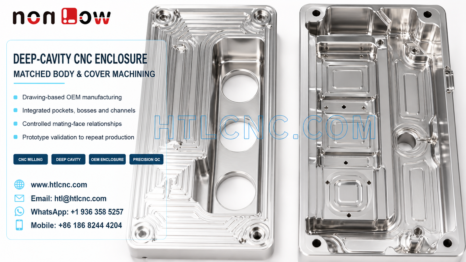
B2B CNC manufacturing for matched enclosure bodies and cover plates with deep cavities, integrated bosses, channels, mounting holes and controlled mating-face relationships.
Matched enclosure bodies and cover plates require more than two individually acceptable machined components. The visible set combines a deep-cavity housing with a corresponding cover, perimeter flanges, recessed channels, multiple pockets, through openings, integral bosses and distributed mounting holes. For an overseas OEM program, the sourcing objective is to control how these features relate across the assembly from prototype approval through repeat production.
HTL CNC provides drawing-based custom CNC machining for equipment manufacturers, product-development companies, contract manufacturers, engineers and procurement teams. Material, tolerances, finish, sealing requirements and final application must follow the customer's released files and approved sample. They cannot be confirmed from a photograph.
Qualifying a Supplier for a Matched Enclosure Set
Supplier qualification should begin with the complete assembly package rather than separate part drawings alone. A useful RFQ includes the body and cover STEP files, controlled 2D drawings, assembly model, specified material, prototype quantity, expected batch size or annual demand, critical characteristics, finishing notes, inspection-document requirements, packaging expectations and delivery destination.
The engineering review should identify which relationships are controlled within each component and which must be verified across the matched set. Procurement teams should also define drawing confidentiality, revision ownership, sample-approval criteria and the process for releasing engineering changes. Programs, fixture references and inspection records should remain linked to the approved revision.
Mating Faces, Perimeter Features and Assembly Relationships
The body and cover have broad perimeter regions that may establish alignment or contact. If the design includes a sealing path, gasket groove or controlled mating surface, the drawing should define the applicable width, depth, flatness, surface condition and edge requirements. These functions should never be assumed from visual appearance.
Machining and deburring must preserve drawing-defined boundaries without rounding critical edges or leaving steps that interfere with assembly. If surface treatment is specified, coating allowance and masked contact areas should be reviewed before quotation because the finished condition—not the raw machined condition—must meet the assembly requirement.
Deep Cavities, Pockets and Integrated Bosses
The housing contains cavities and pockets at several depths together with raised pads, bosses and local channels. Roughing strategy should consider cutter access, chip evacuation, remaining stiffness and finishing allowance. Material can be removed in controlled stages so local mounting features remain supported until their final faces and holes are machined.
Longer tools may be needed in deeper regions, increasing sensitivity to tool deflection and vibration. Internal corner radii, wall heights, tool projection and rest-machining requirements should be reviewed together. The selected route should follow the released geometry rather than a generic tolerance assumption.
Multi-Face Access and Datum Continuity
Visible features are distributed across cavity floors, perimeter faces, side walls and cover openings. The process may use controlled reclamping, indexed positioning or multi-axis machining according to feature access and tolerance relationships. Additional axes are useful only when they reduce risk or improve datum continuity for the actual design.
Workholding should locate from stable surfaces and avoid clamping force that temporarily distorts the enclosure. Prototype fixtures may remain adaptable while engineering changes are open. Repeat orders may justify documented jaw locations, dedicated supports and loading instructions that improve consistency between batches.
Inspection Across the Body-and-Cover Assembly
Inspection should cover both component-level dimensions and drawing-defined assembly relationships. The agreed plan may include cavity and pocket depths, boss heights, mounting-hole locations, opening geometry, perimeter profiles, mating-face relationships and any specified flatness, position, perpendicularity or profile controls.
Calipers, micrometers, height measurement, bore and thread gauges, optical equipment and CMM inspection may be used according to feature geometry. Where the customer requires matched-set verification, inspection fixtures or assembly checks may confirm alignment and interface conditions. Overseas buyers should state whether selected dimensional results, first-article reports, material or finishing documents and batch records are required with shipment.
Finish Control, Identification and Export Packaging
The components can be supplied as machined or with a customer-specified treatment compatible with the released material. Anodizing, plating, passivation, blasting, brushing, polishing, painting or another process should be considered only when included in the RFQ. Cosmetic zones, masked faces, thread protection and color requirements should be documented before production.
Body and cover components should remain identifiable as a controlled set when the purchasing specification requires pairing. Protective separation, trays, labels or other export packaging can prevent metal-to-metal marks and preserve cosmetic surfaces. Batch identification and revision marking should be aligned with the customer's receiving process.
Prototype Validation and Repeat-Order Planning
Prototype quantities allow engineering teams to check enclosure fit, cover alignment, hole relationships, internal clearance, edge condition and finishing assumptions. Procurement teams can evaluate response time, revision control, documentation quality, packaging and delivery performance before approving low-volume ramp-up.
After sample approval, controlled programs, repeatable fixtures, defined inspection points and change management support stable repeat orders. Forecasts or annual demand help the supplier plan raw material, machine capacity, fixture investment, batch size and delivery schedules.
RFQ Package for Engineering and Commercial Review
Send the released body and cover drawings, STEP assembly, specified material, prototype and production quantities, annual demand, critical tolerances, mating or sealing requirements, surface finish, inspection-document scope, packaging needs and delivery destination. HTL CNC can then review the matched enclosure as an assembly rather than quoting two isolated parts.
Website: www.htlcnc.com Email: htl@htlcnc.com WhatsApp: +1 936 358 5257 Mobile: +86 186 8244 4204
Have a part ready for engineering review?
Send your drawing, STEP file, material and quantity directly to HTL CNC for a manufacturing quotation.