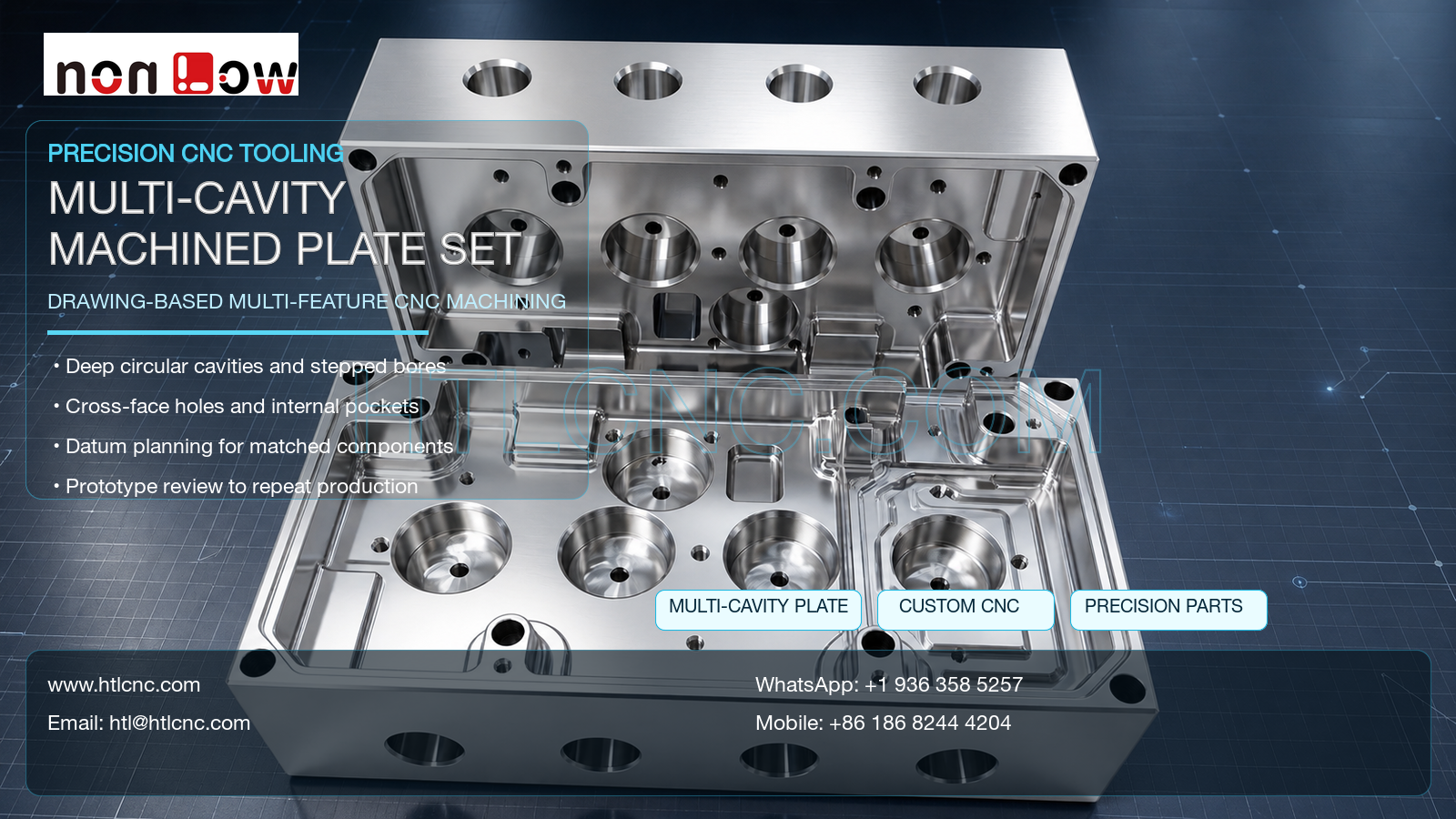
Matched multi-cavity plate set custom CNC machining controls deep circular recesses, stepped bores, cross-face ports and the datum relationship between two precision components.
Matched multi-cavity plate set custom CNC machining is required when two related precision components must combine deep circular recesses, stepped bores, internal pockets, perimeter features and cross-face holes while maintaining a defined relationship at assembly. The pictured set visibly contains two rectangular machined plates with multiple cavity depths, large circular features, small holes, side ports and complex internal boundaries. HTL CNC supports overseas OEMs, product-development teams and equipment manufacturers with custom CNC machining, precision CNC parts, multi-face CNC milling, prototype validation, low-volume production and repeat drawing-based manufacturing. The image does not establish material grade, tolerance, coating, pressure capability, cavity function or final application; these must be specified in the customer's released 2D drawings, STEP files and assembly data.
What Is a Matched Multi-Cavity Plate Set?
A matched multi-cavity plate set is a group of related machined components whose cavities, ports, holes or seating surfaces must work together after assembly. The two pictured plates have different internal layouts, so the manufacturing plan should not treat them as interchangeable copies. Each part needs its own identifier, drawing revision and inspection record, plus a controlled definition of how the pair locates together.
For quotation, the buyer should state whether the plates are supplied only as individual components or as a verified set. That decision affects marking, inspection, cleaning, pairing, packaging and the type of assembly evidence expected from the supplier.
How Should Datums Be Defined Across Two Components?
The released drawings should identify the primary seating face, the secondary and tertiary locating references, and the holes or edges that establish orientation. If cavities or ports on opposite plates must align, the customer should define the relationship through common assembly datums rather than relying on separate coordinate dimensions that may accumulate variation.
A machining route can establish broad reference faces first, then rough and finish the internal geometry while keeping sufficient support. When multi-face access is needed, a qualified 3-axis process with controlled refixturing may be suitable, while indexed 4-axis or 5-axis CNC machining can be evaluated when fewer datum transfers improve access and positional control.
Deep Circular Cavities and Stepped Bores
The visible plates include repeated circular cavities with different diameters and depths. Engineering drawings should distinguish clearance recesses, precision bores, counterbores, threaded entries and noncritical pockets. Diameter, depth, bottom condition, concentricity, surface finish and edge requirements should be assigned only where the assembly needs them.
Tool projection, chip evacuation and remaining wall thickness influence the roughing and finishing sequence. A practical process may remove bulk material in stages, leave controlled finish stock and complete critical diameters after the plate has stabilized. Very small corner radii or deep narrow transitions should be reviewed for cutter access before production pricing is finalized.
Cross-Face Ports, Intersections and Deburring
Large holes are visible on the exterior side faces, while smaller holes enter several cavities. Where drilled or milled features intersect, burrs and retained chips can remain below the visible surface. The manufacturing plan should define access from both directions, edge-break limits, intermediate cleaning and final cleanliness inspection.
No fluid or pneumatic function should be inferred from the photograph. If a port, passage or cavity has a sealing, flow or pressure requirement, the customer must provide the relevant geometry, surface condition, plug or thread specification, cleaning standard and validation method.
Inspection Planning for a Paired Precision Set
A risk-based inspection plan may cover plate flatness, seating-face condition, cavity diameter and depth, stepped-bore relationships, side-port position, perimeter holes, threads, pocket boundaries and drawing-defined geometric controls. Depending on access and tolerance, methods may include calibrated bore and depth gauges, height measurement, optical inspection, CMM probing and customer-approved functional fixtures.
For supplier qualification, first-article results should identify which measurements belong to each plate and which confirm the assembled relationship. Material documents, finish records and production-lot reports should reference the part number, revision, purchase order and pairing or batch identification required by the OEM.
Surface Finish, Cleaning and Protective Packaging
The bright metallic appearance does not confirm an as-machined surface or any particular treatment. Based on the confirmed material and service environment, buyers may specify anodizing, plating, passivation, blasting, polishing, painting or another finish. Drawings should identify masked faces, threads, precision bores and coating-sensitive fits.
Complex cavities and intersecting holes require a defined cleanliness expectation. Protective plugs, cavity covers, single-part separation or formed packaging may be appropriate when finished surfaces and port edges must be protected during export shipment. If the two plates must remain paired, packaging labels should preserve that association through receiving and assembly.
From Prototype Validation to Repeat OEM Supply
Prototype review should confirm that the two plates seat correctly, required cavities and ports align, fasteners can be installed, and adjacent components have the intended clearance. Any leakage, pressure, flow or functional test must use customer-defined methods and acceptance criteria.
After approval, qualified fixtures, controlled CNC programs, first-piece checks, tool-life monitoring and formal revision control support repeat-order consistency. HTL's custom CNC machining service supports drawing review and production planning, while its prototype and low-volume CNC machining service provides a staged route from engineering samples to pilot quantities and recurring OEM supply.
RFQ Package for Matched Multi-Cavity Plate Manufacturing
Send the released 2D drawing and STEP file for each component, plus the assembly model when the pair interacts. Include material, prototype and production quantities, annual demand, common datums, cavity and bore definitions, port and thread specifications, critical tolerances, surface finish, cleanliness or testing requirements, inspection-document scope, pairing rules, packaging, destination and target delivery. HTL CNC can then review manufacturability, inspection coverage and the supply plan for the actual matched multi-cavity plate set custom CNC machining project.
Website: www.htlcnc.com Email: htl@htlcnc.com WhatsApp: +1 936 358 5257 Mobile: +86 186 8244 4204
Have a part ready for engineering review?
Send your drawing, STEP file, material and quantity directly to HTL CNC for a manufacturing quotation.