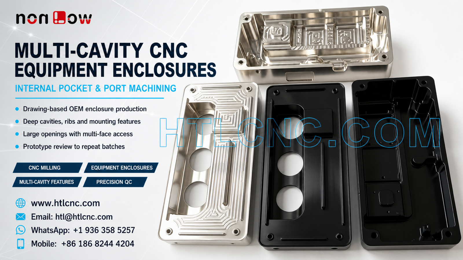
B2B CNC manufacturing for equipment enclosure trays with deep internal cavities, stepped pockets, large openings, mounting features and controlled machined or black-finished surfaces.
Custom equipment programs frequently require more than one enclosure configuration. The visible group includes four tray-style housings with deep internal cavities, stepped pocket patterns, large circular openings, perimeter mounting holes, local ribs and both bright machined and black-finished surfaces. For an overseas OEM, the sourcing challenge is to control each released configuration without losing common datum, inspection and finish requirements across the product family.
HTL CNC provides drawing-based custom CNC machining for equipment manufacturers, product-development companies, contract manufacturers, engineers and procurement teams. The material, dimensions, tolerances, coating specification and end use must follow the customer's released 2D drawings, STEP files and approved samples; they cannot be determined from the photograph.
Qualifying a Supplier for an Enclosure Product Family
Supplier qualification should cover every active part number and revision, not only one representative housing. The RFQ package should identify which variants share stock size, datum strategy, mounting pattern, finishing process or inspection requirements and which features are unique. This helps the supplier evaluate fixture concepts, program management, inspection time and batch planning without combining configurations that require separate controls.
A complete sourcing package should include the released 3D and 2D files, specified material, prototype quantity for each version, production forecast or annual demand, critical characteristics, finish and cosmetic requirements, inspection-document scope, packaging instructions and delivery destination. Drawing confidentiality, ownership of manufacturing data, sample-approval criteria and engineering-change communication should be agreed during onboarding.
Deep Cavities and Stepped Internal Geometry
The housings contain broad cavities with several internal levels, walls, pockets and local raised features. Roughing strategy should consider cutter access, tool projection, chip evacuation, remaining stiffness and finishing allowance. Removing material in controlled stages can preserve support around mounting bosses and thinner internal regions until final faces and pockets are completed.
Internal corner radii, floor depths and wall transitions influence cutter selection and machining time. Longer tools may be required in deeper areas, increasing sensitivity to runout, deflection and vibration. The process route must follow the released model and drawing rather than applying a generic tolerance to visually similar regions.
Large Openings, Perimeter Holes and Multi-Face Access
Several variants include large circular openings together with perimeter holes and side features. Depending on the specified geometry, these may be produced by drilling, interpolation, boring, reaming, threading or controlled profile milling. Their function should not be inferred from appearance.
The important sourcing question is how these openings relate to the internal pockets, outer perimeter and assembly faces. Controlled reclamping, indexed positioning or multi-axis machining may be selected according to datum relationships, tool clearance and volume. The chosen route should reduce unnecessary handling while maintaining stable support and practical inspection access.
Machined and Black-Finished Surface Control
The image shows both bright machined parts and black-finished variants. A customer-specified finish may involve anodizing, plating, passivation, painting or another approved process, but the exact treatment cannot be identified from the image alone. The RFQ should define the treatment, color, gloss, cosmetic zones, masked faces, thread protection and any dimensional allowance required after finishing.
Finish approval should be linked to a documented sample or agreed visual standard when appearance matters. Internal pockets and openings must be cleaned after machining and post-processing. Finished parts should be handled and separated to reduce scratches, edge impacts and metal-to-metal marks before export packaging.
Inspection and Configuration Control
Inspection may cover cavity and pocket depths, wall locations, large opening diameters, mounting-hole positions, perimeter profiles, internal boss heights and relationships between controlled faces. Calipers, micrometers, height measurement, pin or thread gauges, optical equipment and CMM inspection may be used according to feature geometry and drawing tolerances.
For a multi-variant program, the inspection plan and records should identify the exact part number, revision and batch. Overseas buyers should specify whether prototypes or repeat shipments require selected dimensional results, first-article reports, material or finishing documents and batch inspection records. Programs, fixtures and inspection files should remain traceable to the approved revision.
Prototype Approval and Repeat-Order Planning
Prototype quantities allow engineering teams to verify enclosure fit, internal clearance, opening alignment, edge condition and finish requirements for each configuration. Procurement teams can also review responsiveness, confidentiality, documentation, packaging and delivery performance before approving low-volume ramp-up.
After sample approval, controlled programs, repeatable workholding, documented inspection points and change management help maintain consistency across recurring orders. Forecasts by part number support material purchasing, machine-capacity planning, finish-batch coordination and delivery scheduling.
RFQ Information for Engineering Review
Send the released 2D drawing and STEP file for each enclosure version together with the specified material, prototype and production quantities, annual demand, critical tolerances, surface finish, cosmetic expectations, inspection-document scope, packaging needs and delivery destination. HTL CNC can then review the product family as a controlled OEM program rather than quoting isolated reference images.
Website: www.htlcnc.com Email: htl@htlcnc.com WhatsApp: +1 936 358 5257 Mobile: +86 186 8244 4204
Have a part ready for engineering review?
Send your drawing, STEP file, material and quantity directly to HTL CNC for a manufacturing quotation.