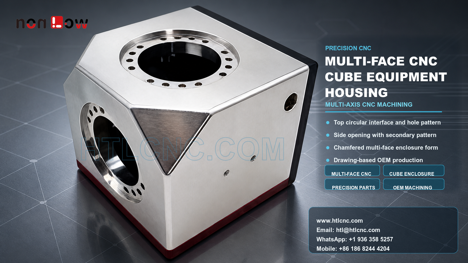
Multi-face CNC cube equipment housing machining coordinates top and side circular interfaces, repeated hole patterns, chamfered faces and cross-side features for drawing-based OEM production.
Multi-face CNC cube equipment housing machining is required when several circular interfaces and secondary features must remain related across a compact three-dimensional body. The pictured housing visibly includes a top circular opening with a repeated surrounding hole pattern, a side circular opening with another hole pattern, a chamfered corner face, side holes and contrasting rear and lower trim. HTL CNC supports overseas OEMs, equipment builders and procurement teams with custom CNC machining, precision CNC parts, multi-axis CNC machining, prototype validation, low-volume production and repeat drawing-based OEM manufacturing. The image does not establish material grade, tolerances, internal function or final application; those requirements must come from the customer's released 2D drawing, STEP model and assembly data.
Why a Cube Housing Requires Cross-Face Datum Planning
A cube enclosure can present important features on several adjacent faces. The top and side circular interfaces may each be acceptable individually but still fail assembly if their axes, seating faces or angular relationships are incorrect. Supplier review should therefore begin with a functional datum structure, not a disconnected list of hole sizes.
Mating-part or assembly information helps identify which face establishes installation, which circular interface locates another component and which openings are clearance-only. That context guides machining sequence, fixture design and inspection evidence.
Top Circular Interface and Repeated Hole Pattern
The top face contains a large circular opening, an annular seating region and repeated surrounding holes. The drawing should define diameter, depth, face condition, hole type, angular spacing and position relative to the selected datums. No fit, sealing condition or tolerance can be inferred from appearance.
Possible operations include face milling, circular interpolation, boring, drilling, reaming or threading according to the released requirements. Inspection may use bore gauges, depth tools, pin or thread gauges, rotary measurement or CMM probing.
Side Circular Opening and Axis Relationship
A second circular interface appears on the adjacent side with its own repeated hole pattern. The key manufacturing question is how this axis relates to the top axis and enclosure faces. A controlled setup or qualified datum transfer is needed when the drawing specifies perpendicularity, position or another cross-feature relationship.
Completing both directions can require refixturing or multi-axis access. HTL's 5-axis CNC machining capability can be evaluated where setup reduction improves access, while a qualified 3-axis or indexed 4-axis route may also be appropriate. Axis count alone does not guarantee quality.
Chamfered Face, Side Holes and Edge Control
The chamfered corner changes both exterior geometry and local tool access. Additional holes on the broad side face add another orientation. Drawings should distinguish locating, threaded and clearance holes, and should specify whether the chamfered area is functional, cosmetic or only provides clearance.
Deburring must remove loose edges without changing controlled circular seats, hole entrances or visible face transitions. If an exterior surface has a cosmetic requirement, handling protection should begin during machining rather than only after final finishing.
Workholding a Compact Multi-Face Enclosure
Fixture contact points must provide rigidity without marking controlled faces or blocking adjacent interfaces. A practical process may establish broad reference surfaces first, rough the circular openings, then finish seating faces and related hole patterns after the body is stable.
HTL's custom CNC machining service reviews stock form, size, quantity, tolerance, finish and inspection scope before defining setups. For repeat production, qualified soft jaws or dedicated fixtures can improve loading consistency and reduce datum-transfer variation.
Inspection Evidence for OEM Supplier Qualification
A risk-based plan may cover top and side bore sizes, annular face condition, hole-pattern position, axis relationship, enclosure-face geometry, side-hole location and drawing-defined geometric controls. Measurement methods can include micrometers, bore gauges, height systems, optical equipment, rotary fixtures and CMM inspection as appropriate.
Overseas buyers may request first-article data or production-lot records for agreed critical characteristics. Report scope, sampling, traceability and retention should be agreed before quotation and tied to the correct part number, revision and lot.
Prototype Validation and Repeat OEM Supply
Prototype review should use actual mating parts where possible. Engineering teams can check circular-interface seating, bolt-pattern alignment, cross-axis orientation, fastener access, side clearance and finish allowance. Any correction should be released through updated 2D and STEP files before ramp-up.
After approval, controlled programs, qualified fixtures, first-piece checks, tool-life management and revision control support repeat-order consistency. HTL's prototype and low-volume CNC machining service supports a staged path from samples to recurring OEM supply.
Finish, Packaging and RFQ Information
The visible surface does not confirm material or final treatment. Customers may specify an as-machined condition, anodizing, plating, passivation, blasting, brushing, polishing, painting or another compatible finish. Masked interfaces, coating allowance, threads and cosmetic zones should be identified.
Send the released 2D drawing and STEP file with material, quantities, annual demand, functional datums, circular-interface definitions, tolerances, finish, inspection-document needs, packaging, destination and delivery target. HTL CNC can then prepare a process, quality and delivery plan based on controlled requirements.
Website: www.htlcnc.com Email: htl@htlcnc.com WhatsApp: +1 936 358 5257 Mobile: +86 186 8244 4204
Have a part ready for engineering review?
Send your drawing, STEP file, material and quantity directly to HTL CNC for a manufacturing quotation.