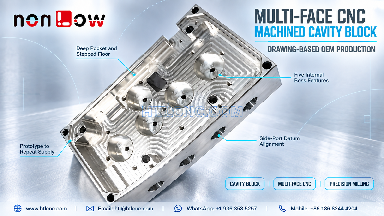
A multi-face CNC machined cavity block links deep-pocket floors, five internal bosses, local recesses and side ports through one controlled datum strategy for prototype and repeat OEM supply.
A multi-face CNC machined cavity block brings deep internal geometry and side-facing interfaces into one thick rectangular component. The pictured part visibly includes a large recessed cavity, stepped floor toolpaths, five rounded internal bosses, a local square pocket, perimeter holes, corner openings and several ports on the side faces. The photograph does not confirm its material grade, tolerance, finish, pressure function or final application, so those requirements must come from the customer's released drawing, STEP model and specifications. HTL CNC provides drawing-based custom CNC machining for overseas OEMs, product-development companies, equipment builders, contract manufacturers, engineers and procurement teams, supporting prototypes, low-volume builds and repeat production.
Why Side Features Change the Entire Process Plan
A deep cavity can often be approached from one main direction, but ports on the side faces introduce additional setups or indexed orientations. Their position may depend on the cavity floor, an internal boss, a perimeter edge or another customer-defined datum. If the machining team treats the top and side faces as separate jobs, small locating errors can accumulate across the datum chain.
Engineering review should identify the primary seating face, secondary locating edges or holes, and the exact feature relationships that affect assembly. The drawing should avoid long chains of unrelated dimensions when a direct geometric control better expresses the requirement. A mating model is useful when port entry, clearance or internal intersection must be checked.
Datum Transfer for Multi-Face CNC Machining
Datum transfer is the method used to preserve one coordinate system while the part is rotated, refixtured or indexed. The suitable route may use a precision fixture, probing, 4-axis positioning or 5-axis CNC machining, depending on part size, access, rigidity, quantity and tolerance. Axis count is only one factor; repeatable location and verification remain essential.
A qualified setup plan defines which surfaces are created first, which features locate later operations, where clamping is permitted and how orientation is confirmed. Side-port machining should be referenced back to stable finished datums rather than to a rough stock edge whenever the drawing requires a close relationship to internal features.
Deep Cavity Milling Around Five Internal Bosses
Five rounded bosses are visible inside the cavity. Material must be removed around them while preserving their diameter, height, position and surrounding floor geometry as specified. Long tool reach, interrupted engagement and reduced support can influence deflection and surface consistency.
A practical deep cavity milling sequence may rough the open regions, leave balanced finishing stock, then complete walls, floors, bosses and local recesses in a controlled order. The exact cutters, toolpaths and cutting conditions depend on the specified material and released tolerances. Intermediate checks may be appropriate before a final pass when a feature would be difficult to recover after excess material is removed.
Stepped Floors, Local Pockets and Achievable Corners
The cavity floor contains several levels and visible contour toolpaths. A small square pocket and local channels add different tool-access constraints. The drawing should identify which depths and transitions are functional, define achievable internal corner radii and state whether floor roughness is important to assembly or another customer-defined requirement.
A theoretical sharp internal corner in a model cannot be produced by ordinary end milling. If a mating square component requires relief, the design may use an approved radius, corner relief or another specified process. Edge-breaking instructions should also protect datum shoulders and small openings from excessive rounding.
Port Intersections and Deburring Access
When a side hole enters a cavity, burrs may form at the internal breakthrough where direct access is limited. The RFQ should specify whether ports are through, blind, threaded, counterbored or otherwise controlled, along with depth, diameter, thread standard and positional requirements.
Deburring methods should remove loose material without changing port size or damaging adjacent machined floors. Inspection planning should account for the intersection, not just the accessible outer opening. Where cleanliness is functionally important, the customer should define the required cleaning and packaging standard rather than relying on appearance alone.
Inspection Strategy for a Thick Cavity Block
Risk-based inspection may cover overall dimensions, cavity depth, boss diameter and height, pocket location, perimeter-hole pattern, side-port position, face relationships, flatness, profile or perpendicularity only where required by the drawing. Measurement can combine calibrated hand tools, depth and height systems, pin or thread gauges, optical equipment and CMM inspection.
The inspection method should reproduce the drawing's datum scheme. Measuring the side ports from an easy but nonfunctional edge can produce data that does not represent assembly performance. First-article documentation should identify the exact part number, revision, material lot, production lot and measurement condition.
Material and Finish Requirements Belong in the RFQ
The bright silver appearance does not identify a specific alloy or surface treatment. Buyers should provide the exact material standard and condition, any approved equivalents, certification scope, heat-treatment requirement, surface finish, masking zones and cosmetic acceptance criteria. HTL will not replace a customer material callout with an estimate based on a photograph.
If a coating or conversion process is required, the drawing should state whether dimensions apply before or after treatment and which ports, bores or contact areas must remain free of buildup. Post-process inspection may be needed where treatment can influence a functional interface.
Prototype Review Before Repeat Orders
A prototype should be evaluated with its mating parts when possible. The engineering team can confirm cavity clearance, boss alignment, side-port entry, fastener access, seating and edge condition. Any resulting change should update the 2D drawing and STEP model together, with a new revision released before further production.
After approval, controlled CNC programs, qualified fixtures, setup records, first-piece inspection and lot-linked documentation support low-volume ramp-up and repeat OEM supply. HTL's prototype and low-volume CNC machining service provides a staged path from initial verification to recurring orders.
Sourcing and Export Delivery Questions
Procurement teams should ask how the supplier protects customer drawings, separates obsolete revisions, controls inspection equipment and manages outside finishing when required. Annual demand, order frequency, batch size, destination and target schedule help HTL plan stock, machine capacity, inspection and export packaging.
The cavity opening and side ports should be protected from impact and contamination in transit. Part-to-part contact may require sleeves, separators or a formed tray based on the actual finish and weight. Labels should preserve part number, revision, quantity and lot traceability.
RFQ Checklist for a Multi-Face CNC Machined Cavity Block
Send the released 2D drawing and STEP file, exact material specification, prototype and production quantities, annual demand, functional datum scheme, critical cavity depths, boss requirements, side-port sizes and locations, tolerances, edge and cleaning requirements, finish specification, inspection-document scope, packaging, destination and delivery schedule. Include mating models when port alignment or internal clearance is critical. HTL CNC can then review the multi-face CNC machined cavity block and propose a controlled machining, inspection and repeat-supply plan.
Website: www.htlcnc.com Email: htl@htlcnc.com WhatsApp: +1 936 358 5257 Mobile: +86 186 8244 4204
Have a part ready for engineering review?
Send your drawing, STEP file, material and quantity directly to HTL CNC for a manufacturing quotation.