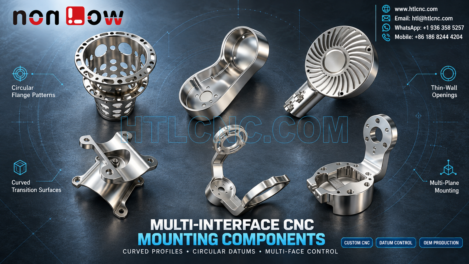
Multi-interface CNC mounting components connect circular flange patterns, curved transition surfaces, thin-wall openings and multi-plane mounting features through controlled datum transfer.
Multi-interface CNC mounting components combine circular references with curved, open and prismatic mounting geometry. The pictured set visibly contains six different parts: a perforated cylindrical form, an elongated rounded cavity housing, a radial-groove circular component with a short stem, a curved saddle bracket, an open ring-and-arm structure and a deep circular body with an upright flange. The image does not establish whether these parts share one assembly, or confirm their materials, tolerances, finishes or end uses. Those requirements must come from released 2D drawings, STEP models and assembly data. HTL CNC supports overseas OEMs, equipment builders, product-development companies, engineers and procurement teams with drawing-based custom CNC machining, prototypes, low-volume builds and repeat production.
Translate Circular Datums into Mounting Coordinates
A common engineering challenge is relating a round bore, flange or ring to flat mounting faces and offset holes. The buyer should identify which circular feature establishes the main axis, which surface controls axial seating and which hole or flat controls clocking. Without that hierarchy, each setup may be locally accurate while the final interfaces are misaligned.
Drawings should use functional datums and geometric controls only where assembly requires them. HTL's custom CNC machining service reviews these relationships before workholding and setup order are finalized.
Control Flange Hole Patterns Around a Shared Axis
Several visible parts include holes arranged around a circular interface. Hole diameter alone is not enough when mating depends on bolt-circle position, angular spacing, counterbore condition or perpendicularity to a seating face. The RFQ should distinguish locating holes, clearance holes, threaded holes and noncritical openings.
A first-article report can identify holes by clock position and relate the complete pattern to the main circular datum. Pin gauges, height systems, optical equipment, CMM inspection or a customer-approved mating fixture may be used according to tolerance and access.
Curved Transition Surfaces Need a Defined Inspection Strategy
The elongated housing and saddle-style bracket visibly include broad curved blends between circular and prismatic regions. A rendered model may communicate the shape, but the drawing should state whether the contour is cosmetic, clearance-related or functionally controlled.
Profile tolerances, section dimensions or approved comparison data may be more useful than many disconnected point dimensions. Tool-path smoothing and stable cutter engagement can help preserve the intended surface while avoiding visible faceting or blend marks.
Thin-Wall Openings Change Stiffness During Machining
The perforated cylindrical component and open ring structures contain repeated windows and narrow remaining sections. Material removal changes stiffness throughout the cycle, so roughing, support and finishing order must be planned together. Excessive clamping force can temporarily distort a thin wall and allow it to move after release.
Window dimensions, web thickness, internal radii and edge-break requirements should be explicit. Deburring must remove loose material without enlarging openings, thinning a web or rounding a locating edge.
Multi-Face Access and Datum Transfer
The visible parts include holes, pockets and interfaces approached from different directions. A qualified 3-axis route with controlled refixturing, indexed 4-axis work or 5-axis CNC machining may be selected from the complete geometry, tolerance and quantity.
The objective is to reduce uncertain datum transfer, not simply to use more axes. Fixtures, soft jaws and support points should keep functional circular datums available while protecting finished curves, thin walls and flange faces.
Machine Cavities Without Losing Ring and Wall Relationships
The elongated and deep circular bodies contain open cavities with local holes and transitions. Tool reach, holder clearance, chip evacuation and floor access must be evaluated before quotation. Internal corner radii should match practical cutter diameters unless a sharper corner has a documented function.
Where a cavity intersects a side opening or hole, the process plan should address hidden burrs and retained chips. Cleaning and inspection should cover the full internal path rather than only the visible entrance.
Inspect Each Part Number as Its Own Controlled Product
A mixed family image does not mean the parts share one tolerance plan. Each part number needs a separate revision, process traveler, inspection record and acceptance criteria. A risk-based plan may cover bore size, flange flatness, hole-pattern position, curved profile, cavity depth, wall thickness, mounting-face relationships and drawing-defined geometric controls.
Supplier qualification should define required first-article data, material records, finish documents, sampling level and lot traceability. Reports should identify the exact drawing revision and measuring equipment used.
Material and Finish Cannot Be Inferred from Appearance
The bright metallic surfaces do not prove aluminum, stainless steel, plating, passivation or polishing. The RFQ should provide the exact material standard and condition, heat treatment, surface process, coating thickness, masking zones, cosmetic requirements and certificate scope.
Coating-sensitive bores, flange faces and holes may need allowance, masking or post-finish inspection. Cosmetic zones should be identified, and approved samples can clarify acceptable texture and handling marks where appearance matters.
Prototype Validation for Multi-Interface Assembly
Prototype quantities allow engineering teams to check bore fit, flange clocking, hole-pattern alignment, curved-surface clearance, fastener access and the proposed inspection method with actual mating components. Any design change should update both the 2D drawing and STEP model under one controlled revision.
HTL's prototype and low-volume CNC machining service supports samples and pilot quantities. After approval, qualified programs, controlled fixtures, first-piece checks, tool-life rules and formal revision control support repeat OEM supply.
Packaging and Delivery Planning
Open rings, thin walls, flange edges and approved cosmetic curves can be damaged by metal-to-metal contact. Individual sleeves, separators, trays or shaped protection may be selected according to geometry and finish. Labels should identify part number, revision, quantity and lot.
For sourcing planning, buyers should provide annual demand, release frequency, destination and target schedule. This lets machining, external finishing, inspection workload and export packaging be coordinated without mixing revisions or part numbers.
RFQ Checklist for Multi-Interface CNC Mounting Components
Send the released 2D drawing and STEP file for each component, assembly or mating-part data, a part-number and revision matrix, exact material, prototype and production quantities, annual demand, functional circular datums, flange hole patterns, curved-profile requirements, thin-wall and opening dimensions, cavities, tolerances, finish, inspection-document scope, packaging, destination and schedule. HTL CNC can then prepare a controlled manufacturing and quality plan for the multi-interface CNC mounting components.
Website: www.htlcnc.com Email: htl@htlcnc.com WhatsApp: +1 936 358 5257 Mobile: +86 186 8244 4204
Have a part ready for engineering review?
Send your drawing, STEP file, material and quantity directly to HTL CNC for a manufacturing quotation.