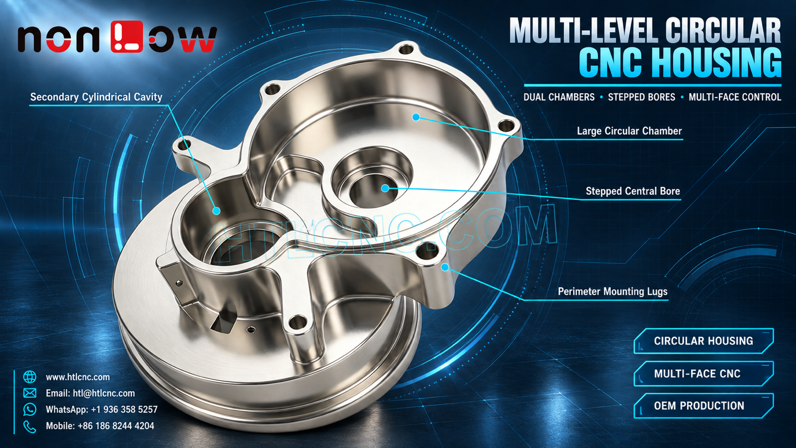
A multi-level circular CNC housing coordinates two connected chambers, a stepped central bore, different floor heights and perimeter mounting lugs through one controlled datum strategy.
A multi-level circular CNC housing combines rotational geometry with irregular milled features in one integrated body. The visible part has one large circular chamber, a smaller adjacent cylindrical cavity, a stepped central bore, a curved internal divider, a side opening and several perimeter mounting lugs. These features do not prove a specific material, tolerance, finish, sealing duty or final application; the released 2D drawing, STEP model and assembly data remain authoritative. HTL CNC supports overseas OEM teams with drawing-based custom CNC machining, prototypes, low-volume production and repeat supply.
Build the Datum Plan Around Assembly Function
Before programming, the buyer should identify the primary seating face, the axis that locates the housing and the clocking feature used in assembly. A practical datum hierarchy can keep the main chamber, stepped bore, secondary cavity and lug holes related to the same functional references instead of treating each setup independently.
The drawing should distinguish critical interfaces from clearance or cosmetic geometry. This prevents unnecessary tolerance on nonfunctional surfaces while protecting the relationships that determine fit. HTL's custom CNC machining service reviews these relationships before a production route is selected.
Control Chamber Floors at Different Heights
The two visible chambers do not share one simple floor level. Multiple steps, wall heights and blends create a depth stack that can affect assembly clearance and minimum wall thickness. The drawing should define each functional depth from a stable reference face rather than relying on chained dimensions across several steps.
Roughing may leave uniform stock on chamber floors and walls before finish passes. Tool reach, holder clearance, chip evacuation and part stiffness must be considered together, especially near the curved divider and the deeper secondary cavity.
Relate the Stepped Central Bore to the Main Chamber
The central opening visibly includes more than one diameter and height. Its complete internal form, fit and tolerance cannot be confirmed from the image. The drawing should specify bore diameters, depths, shoulders, edge breaks and any coaxiality, runout or perpendicularity required relative to the seating face and main circular axis.
Depending on size and tolerance, the feature may be produced by circular interpolation, boring, reaming or a staged combination. Inspection can use bore gauges, depth instruments, CMM probing or customer-approved functional gauges.
Machine the Secondary Cavity and Curved Divider Without Distortion
The smaller cylindrical cavity and curved connecting wall restrict cutter approach. A process plan should preserve support during roughing and avoid finishing thin walls too early. Internal corner radii should be compatible with practical cutter diameters unless a smaller radius has a documented functional reason.
Deburring deserves its own plan because edges around the side opening, divider and intersecting cavity can be difficult to reach after all surfaces are finished. The inspection and cleaning method should confirm that no loose chips or burrs remain in hidden transitions.
Transfer Datums Across Multiple Machining Directions
The front chambers, outer circular profile, side opening and lug holes may require more than one tool direction. A qualified 3-axis process with controlled refixturing, indexed workholding or 5-axis CNC machining may be evaluated from the complete model, tolerance and quantity.
The objective is not to maximize axis count; it is to minimize uncertain datum transfer. Soft jaws, a dedicated nest or a locating fixture can reference previously finished geometry while protecting chamber rims and polished surfaces from clamp marks.
Number and Inspect the Perimeter Mounting Lugs
The mounting ears are distributed around an irregular outline, so each lug and hole should be clearly numbered on the inspection plan. Hole diameter alone is insufficient when assembly also depends on true position, spacing, edge distance, lug thickness and seating-face relationship.
A first-article report can identify every lug by clock position and relate its hole to the established datum system. Pin gauges, height equipment, optical measurement, CMM inspection or a customer-approved mating fixture may be used according to tolerance and access.
Verify the Side Opening and Edge Conditions
A side opening is visible near the lower-right region, but the image does not establish whether it is a port, clearance window or machining access. The drawing should define its profile, location, wall intersections and permitted edge breaks.
Intersecting features can leave burrs on surfaces that are hard to inspect directly. Process control should include visual or optical access, cleaning and a documented acceptance method when the opening communicates with an internal chamber.
Material and Finish Must Come from the Specification
The bright metallic appearance does not prove aluminum, stainless steel, plating or polishing. The RFQ should provide the exact material standard and condition, heat treatment, finish, coating thickness, masking zones, cosmetic criteria and certificate requirements.
If chamber rims, bores or lug faces are functional, the buyer should state whether dimensions are accepted before or after finishing. Coating allowance and masking decisions can materially change bore fit, floor height and seating flatness.
Prototype Validation Before Repeat Supply
Prototype parts can confirm chamber clearance, bore fit, lug-hole alignment, side-opening access and the selected inspection method with actual mating components. Any change after assembly testing should update the 2D drawing and STEP model under the same revision.
HTL's prototype and low-volume CNC machining service supports engineering samples and pilot quantities. After approval, controlled programs, qualified fixtures, first-piece checks, tool-life monitoring and revision control help maintain consistency across repeat releases.
RFQ Checklist for a Multi-Level Circular Housing
Send the released 2D drawing and STEP file, assembly model, exact material, prototype and production quantities, annual demand, functional datum scheme, chamber diameters and floor depths, stepped-bore details, divider geometry, side-opening definition, lug-hole positions, tolerances, surface finish, inspection-document scope, cleanliness requirements, packaging, destination and target schedule. HTL CNC can then prepare a controlled machining and inspection plan for the multi-level circular CNC housing.
Website: www.htlcnc.com Email: htl@htlcnc.com WhatsApp: +1 936 358 5257 Mobile: +86 186 8244 4204
Have a part ready for engineering review?
Send your drawing, STEP file, material and quantity directly to HTL CNC for a manufacturing quotation.