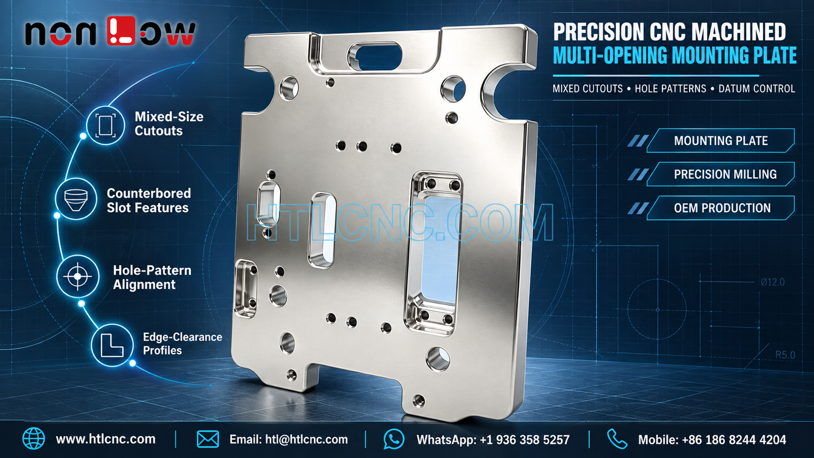
A multi-opening CNC machined mounting plate combines mixed cutouts, counterbored slot features, repeated hole groups and edge-clearance profiles that require one controlled coordinate system.
A multi-opening CNC machined mounting plate can concentrate many assembly interfaces into one precision-milled component. The pictured plate visibly includes large semicircular edge clearances, a bottom U-shaped clearance, multiple circular holes, elongated rounded slots, recessed or counterbored slot features and raised sections along the upper edge. The photograph does not establish the material grade, plate thickness, flatness tolerance, surface treatment, load requirement or final application. Those requirements must come from the buyer's released 2D drawing, STEP model and assembly specification. HTL CNC supports overseas OEMs, product-development companies, equipment builders, engineers and procurement teams with drawing-based custom CNC machining, prototype mounting plates, low-volume production and repeat supply.
Organize the Drawing by Feature Families
A plate with many unrelated-looking openings is easier to review when the drawing groups features by function. The RFQ should identify locating holes, fastener holes, clearance holes, elongated adjustment slots, connector or module cutouts and ordinary reliefs. Feature IDs should match the CAD model, drawing and first-article report.
This organization helps prevent an opening from being quoted or inspected with the wrong requirement. A circular hole that appears similar to another may have a different fit, depth or positional relationship. HTL's custom CNC machining service uses the released feature definitions to plan tools, setups and measurement methods.
Establish One Coordinate System for Mixed Openings
The plate includes holes and slots distributed across a broad face. Individual diameters and slot widths can pass inspection while the complete pattern is shifted or rotated relative to the mating assembly. The drawing should establish stable primary, secondary and tertiary datums, then locate critical feature groups from that system.
Basic dimensions with position or profile controls can communicate pattern relationships more clearly than long chained dimensions. If the upper raised regions, side clearances or bottom opening locate the part in assembly, that function should be stated rather than inferred from appearance.
Counterbored Slot Features and Fastener Access
Several elongated features visibly include recessed ends or local pockets with smaller holes. Their exact depth, thread status, fastener type and function cannot be confirmed from the image. The 2D drawing should define slot width and length, end radii, recess depth, hole size, countersink or counterbore geometry and whether dimensions apply before or after finishing.
Tool access and cutter diameter should be reviewed together. A pocket that must accept a fastener head needs sufficient floor depth and corner clearance without weakening nearby walls. Deburring should remove sharp edges while preserving the slot width and the seating surface around each hole.
Edge-Clearance Profiles Need Assembly Context
Large semicircular clearances are visible on both sides, and a U-shaped clearance interrupts the lower edge. These profiles may provide space for mating components, motion or cable paths, but the photograph does not prove their purpose. Mating models and assembly orientation help the supplier check clearance without guessing.
The drawing should define profile size, location, edge radii and the relationship to the plate datum system. When a clearance opens to the outside edge, workholding and cutting sequence should avoid vibration or local distortion in the remaining arms and corners.
Plate Thickness, Flatness and Machining Sequence
A mounting plate often needs a stable seating face even when many openings remove material unevenly. The RFQ should specify stock thickness, finished thickness, flatness zones and any parallelism or profile requirements. Broad cosmetic faces and functional mounting faces should be identified separately.
A suitable route may establish a reference face, rough high-volume cutouts while support remains, finish important slots and hole patterns from a common coordinate system, then verify the plate after unclamping. The actual sequence depends on material, starting stock, feature depth, tolerance and quantity.
Setup Choice: 3-Axis, Indexed Work or 5-Axis Access
Most visible face features may suit controlled 3-axis CNC milling. Backside steps, side holes or restricted cutter access not shown in the photograph may require a second setup, indexed 4-axis positioning or 5-axis CNC machining. Machine-axis count should follow the complete model rather than the front view alone.
When refixturing is required, the process plan should explain how the datum system is transferred and requalified. Finished holes or purpose-machined locating surfaces can support repeatable setups when their tolerance and accessibility make them suitable.
Inspection Map for Hole Patterns and Slots
A risk-based first-article report may cover overall profile, thickness, flatness, side and bottom clearances, circular-hole diameters, slot width and length, recess depths, hole-pattern position and drawing-defined geometric controls. Measurement may combine calibrated hand tools, height systems, pin gauges, depth gauges, optical inspection and CMM equipment.
A numbered inspection map is particularly useful for plates with many similar holes. It lets engineering and procurement teams trace each reported result back to the released drawing and avoids ambiguous comments such as 'third hole from the left.' The report should also identify part number, revision, lot and measurement equipment.
Material and Finish Must Be Released, Not Inferred
The bright metallic appearance does not prove aluminum, stainless steel, plating, anodizing, passivation or polishing. The RFQ should provide the exact material standard and condition, permitted substitutions, finish process, coating allowance, masking zones, cosmetic criteria and certification scope. HTL will not infer a material or treatment from reflectivity.
Close-fit holes, threaded features, counterbores and seating surfaces may require masking or post-finish verification. The drawing should state whether critical dimensions apply before or after finishing and identify surfaces that must remain free of contact marks.
Prototype Fit Checks and Revision Control
Prototype plates allow the OEM team to check mating-part clearance, fastener access, slot adjustment range, hole alignment, edge-clearance profiles and assembly orientation with actual components. Any resulting geometry change should update both the 2D drawing and STEP model under a new revision.
HTL's prototype and low-volume CNC machining service supports engineering samples before recurring production. After approval, controlled programs, qualified fixtures, first-piece checks and revision-specific inspection plans help preserve the approved layout.
Repeat Production, Packaging and Supplier Qualification
Finished plate faces and narrow sections around open-edge clearances can be damaged by impact or metal-to-metal contact. Packaging may use protective film, separators, sleeves or formed trays selected from the actual geometry and finish. Labels should show part number, revision, quantity and production lot.
Supplier qualification should also cover drawing confidentiality, obsolete-revision quarantine, inspection capability and corrective-action records. Annual demand, release cadence, destination and target schedule help the supplier plan stock, machine capacity, outside processing, inspection and export packing.
RFQ Checklist for a Multi-Opening CNC Machined Mounting Plate
Send the released 2D drawing and STEP file, assembly orientation and mating models, exact material, prototype and production quantities, annual demand, datum system, hole and slot definitions, recess depths, edge-clearance profiles, thickness and flatness requirements, tolerances, edge breaks, finish and cosmetic zones, inspection-document scope, packaging, destination and delivery schedule. HTL CNC can then review the multi-opening CNC machined mounting plate and propose a controlled milling, inspection and repeat-supply plan.
Website: www.htlcnc.com Email: htl@htlcnc.com WhatsApp: +1 936 358 5257 Mobile: +86 186 8244 4204
Have a part ready for engineering review?
Send your drawing, STEP file, material and quantity directly to HTL CNC for a manufacturing quotation.