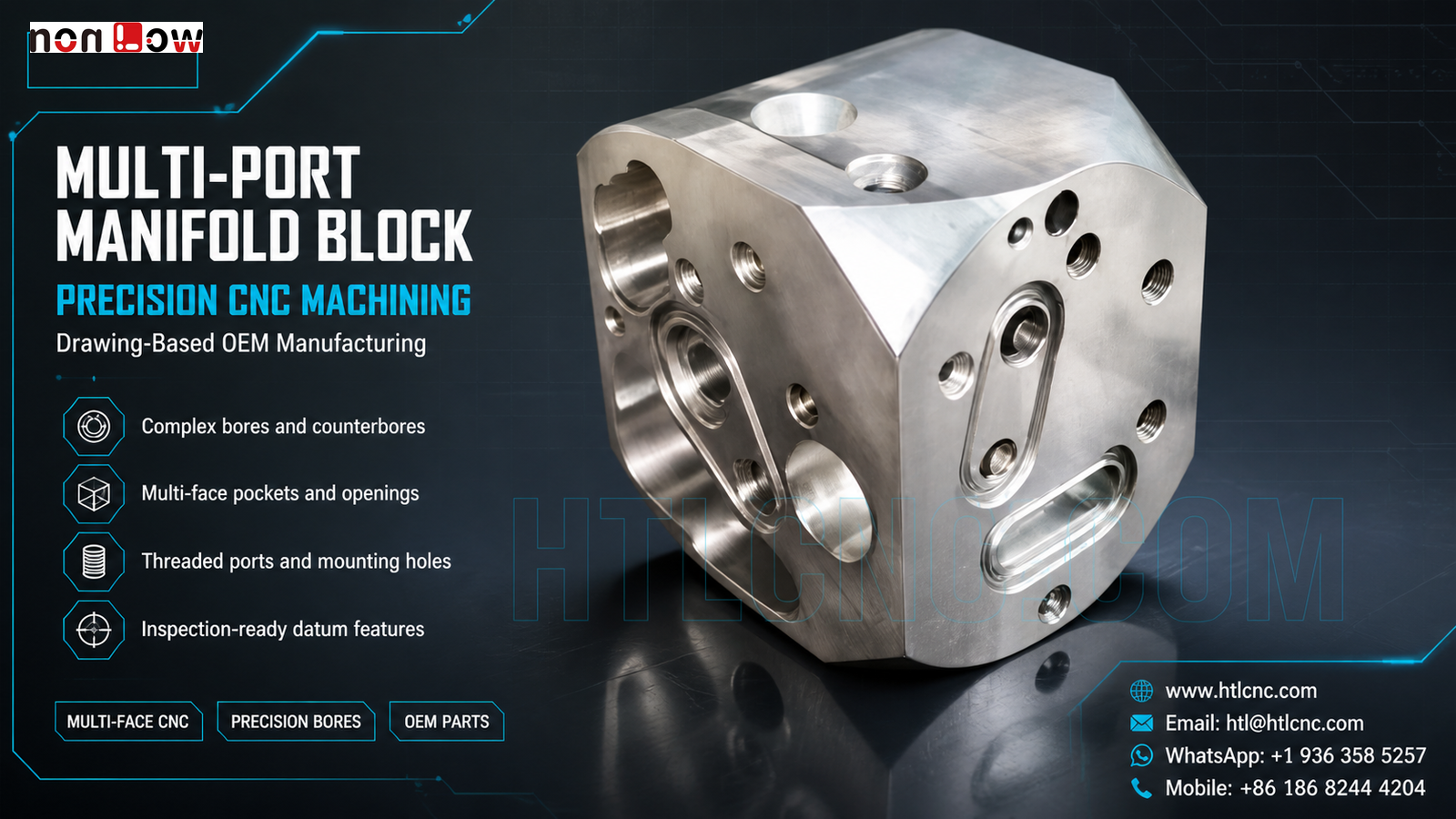
Multi-port manifold block precision CNC machining coordinates large bores, threaded ports, counterbores and multi-face openings around one controlled datum strategy.
Multi-port manifold block precision CNC machining is needed when an OEM component brings large bores, threaded ports, counterbores, cross-face holes and recessed openings into one compact body. The pictured part visibly has machined features on several adjacent faces, including circular bores, tapped ports, an elongated recessed opening and local mounting holes. HTL CNC supports overseas equipment builders, product-development companies, engineers and procurement teams with custom CNC machining, precision CNC parts, multi-face milling, prototype validation, low-volume production and repeat drawing-based OEM manufacturing. The image does not confirm material grade, tolerance, pressure rating, finish or final use; those requirements must come from the customer's released drawing, STEP model and application specification.
Why a Multi-Port Block Needs an Interface-Led Review
A block with many openings is not difficult merely because it has many holes. The sourcing risk comes from the relationships between faces: which bore locates the assembly, which surface seats against another component, which ports intersect internal passages and which holes are only for fastening. Supplier qualification should therefore begin with an interface map rather than a generic request for CNC milling.
The RFQ should identify the primary mounting datum, orientation datum, functional bore axes, mating faces, threaded connections and any passage relationships. An assembly model or interface drawing helps the machining supplier distinguish critical relationships from clearance features and cosmetic surfaces.
Multi-Face CNC Process Planning
Features on the top, front and side faces require deliberate setup planning. Depending on part size, tool reach, quantity and drawing relationships, production may use indexed 4-axis work, 5-axis CNC machining or qualified refixturing. The correct route is the one that reduces unnecessary datum transfer while maintaining safe clamping and inspection access.
Roughing can establish the external form and remove bulk material before critical bores and seating faces are finished. Where intersecting passages or deep openings exist, the sequence should also consider chip evacuation, burr access and tool deflection. Axis count alone does not establish capability; the released process must connect every setup back to the drawing datums.
Bores, Counterbores and Threaded Ports
The visible component includes bores of different diameters and depths, some with counterbored or threaded detail. The drawing should define fit class, depth, thread form, effective engagement, edge break and positional relationship only where required by the assembly. Treating every opening as a general hole can lead to quotation ambiguity and inspection gaps.
Cross holes and internal intersections need an agreed deburring method. A sharp internal edge may retain chips, while uncontrolled hand finishing can change a functional diameter or sealing face. When cleanliness matters, the customer should specify cleaning and acceptance requirements rather than relying on appearance alone.
Datum Relationships and Inspection Evidence
A useful inspection plan follows product function. It may cover the primary seating face, large-bore size and axis, perpendicularity between adjacent interfaces, port location, counterbore depth, thread acceptance and drawing-defined geometric controls. Measurement can combine calibrated bore and depth gauges, pin and thread gauges, optical systems, CMM probing and dedicated fixtures according to feature access and tolerance.
For first-article approval, the report should identify part number, drawing revision, measurement condition and material lot when required. Repeat OEM production benefits from controlled programs, qualified fixtures, first-piece approval, tool-life monitoring and revision control so later orders follow the same released definition.
Surface Finish, Cleaning and Packaging
The bright metal appearance does not prove a material or finish. After the OEM defines material and operating environment, options may include anodizing, plating, passivation, blasting, polishing or another specified process. Bores, threads, seating faces and datum surfaces affected by coating thickness should be marked for masking, allowance or post-finish verification.
A multi-port block can trap chips or finishing media. Cleaning level, permissible edge breaks, protective plugs and packaging should be part of the purchasing specification. Export packaging should prevent machined faces and threaded interfaces from contacting neighboring parts during transport.
Prototype Validation Before Repeat Supply
Prototype quantities give the engineering team an opportunity to verify mating-component fit, passage alignment, fastener access, thread engagement and the proposed inspection method. Any pressure, sealing, load or life test requires customer-defined conditions and acceptance criteria; performance cannot be inferred from the photograph.
After sample approval, the same released revision can move into low-volume ramp-up and repeat production. HTL's custom CNC machining service supports manufacturability review and process planning, while prototype and low-volume CNC machining provides a controlled path from engineering samples to recurring supply. Buyers can include annual demand, delivery cadence, packaging and inspection-document expectations during onboarding.
RFQ Checklist for a Multi-Port Manifold Block
Send the released 2D drawing, STEP file and relevant assembly or flow-interface information. Include material, prototype quantity, production quantity or annual demand, datum scheme, critical bore and port relationships, thread definitions, tolerances, finish, cleanliness, inspection-document scope, revision status, packaging, destination and target schedule. HTL CNC can then review the actual multi-port manifold block precision CNC machining project with a defined manufacturing and quality plan.
Website: www.htlcnc.com Email: htl@htlcnc.com WhatsApp: +1 936 358 5257 Mobile: +86 186 8244 4204
Have a part ready for engineering review?
Send your drawing, STEP file, material and quantity directly to HTL CNC for a manufacturing quotation.