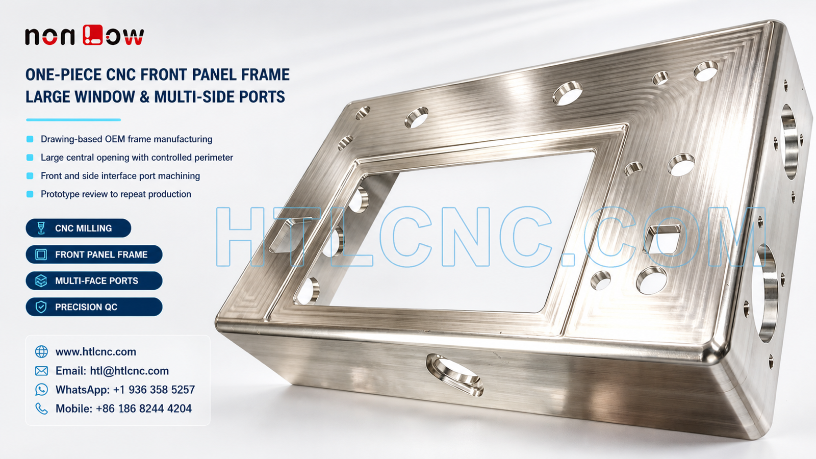
Drawing-based B2B CNC manufacturing for one-piece equipment front-panel frames with a large central window, front-face hole patterns and multi-side interface ports.
A one-piece equipment front-panel frame can combine a broad central window, multiple front-face holes, small rectangular cutouts and large interface ports on adjacent side walls. Keeping these features in one machined body can reduce separate-part alignment work, but it also makes the datum plan, workholding sequence and inspection strategy more important. The visible component shows this multi-face architecture; its material, dimensions, tolerances and intended use must be defined by the customer's released files.
HTL CNC supports drawing-based custom CNC machining for overseas OEMs, equipment manufacturers, product-development companies, engineers, contract manufacturers and procurement teams. We review the actual 2D drawing and STEP model before recommending a process route. A product photograph can confirm visible geometry, but it cannot establish material grade, tolerance, coating, certification or final application.
Supplier Onboarding Starts with a Controlled RFQ Package
For supplier qualification, buyers should provide the released STEP file, controlled 2D drawing, specified material, prototype quantity, expected batch size or annual demand, critical dimensions, surface-finish requirements, inspection-document scope, packaging expectations and delivery destination. The package should identify the current part number and revision so quotations and engineering comments remain traceable.
Confidentiality terms, drawing ownership, sample-approval criteria and engineering-change communication should be agreed before production data is released. When several product variants share the same outer frame but use different port patterns, each configuration should remain separately controlled rather than being treated as an interchangeable visual version.
Large Central Window and Perimeter Stability
The large rectangular opening removes support from the middle of the component and leaves a relatively broad but interrupted perimeter frame. Roughing and finishing order should consider how the remaining material responds as the window, outer profile and local recesses are machined. Controlled stock can be retained during early operations before the drawing-defined window and perimeter are finished.
Workholding should support the component without pulling the frame away from its free-state condition. Clamping force, support location, tool engagement and cutting sequence can all affect the relationship between the window edge, front face and side walls. The required window size, corner radii, profile, flatness or positional relationships must come from the drawing rather than from the visible appearance.
Front-Face Holes and Rectangular Cutouts
The front surface contains circular holes of different visible sizes together with smaller rectangular openings. Depending on the released design, these features may require drilling, interpolation, boring, reaming, threading, counterboring or profile milling. Their function should not be inferred from the photograph.
The engineering review should identify which holes locate mating components, which provide clearance and which belong to cosmetic or service areas. Hole position relative to the main window and selected datums may be more important than an isolated diameter. Rectangular cutouts also require documented corner radii, edge conditions and any fit requirement for switches, displays, connectors or customer-specific hardware.
Multi-Side Interface Port Machining
Large circular ports and smaller holes are visible on the adjacent side walls. These features introduce datum transfer between the primary front face and multiple side orientations. Controlled reclamping, indexed positioning or multi-axis access may be selected according to the actual feature relationships, cutter clearance, wall depth and production volume.
Reducing unnecessary setups can improve consistency, but the correct machine route depends on the drawing rather than on a generic preference for a particular axis count. When a side port must align with an internal component or a front-face feature, that relationship should be stated as a drawing control and included in first-article inspection.
Edge Condition, Surface Finish and Cosmetic Review
The frame includes rounded outer edges, chamfered transitions and machined faces that may remain visible in the finished assembly. Deburring should remove sharp edges without enlarging openings, changing small cutouts or rounding drawing-controlled corners. Cosmetic zones and functional sealing or mounting faces should be identified separately.
Parts may be supplied as machined or with a customer-specified treatment compatible with the released material. Anodizing, plating, passivation, blasting, brushing, polishing, painting or another process should be quoted only when defined in the RFQ. Buyers should specify color, gloss, masking, thread protection, coating allowance and visual acceptance criteria where applicable.
Inspection Across Front and Side Datums
An agreed inspection plan may cover the main window profile, perimeter width, face relationships, hole diameters, hole positions, rectangular cutouts, side-port locations, wall dimensions, edge condition and any drawing-specified geometric controls. Calipers, micrometers, height measurement, pin or thread gauges, optical equipment and CMM inspection may be selected according to feature geometry and tolerance.
For overseas supplier approval, prototype or batch deliveries may require selected dimensional results, a first-article report, material or finishing documents and lot-level inspection records. Each report should identify the exact part number, drawing revision and production batch. Measurement strategy should reflect the functional datum system rather than checking unrelated features independently.
Prototype Validation and Repeat Production
Prototype quantities give engineering teams an opportunity to verify window clearance, side-port alignment, hardware fit, assembly access, edge condition and finishing assumptions. Procurement teams can also evaluate communication speed, document control, confidentiality, packaging and delivery performance before approving a supplier for repeat orders.
After the sample is approved, controlled programs, documented fixture locations, defined inspection points and revision management support low-volume ramp-up and recurring production. Annual forecasts help plan raw material, machine capacity, fixture investment, finishing batches and export delivery schedules. Changes to port patterns or cutout geometry should trigger a documented review rather than an informal program edit.
RFQ Information for Engineering Review
Send the released 2D drawing and STEP file together with the specified material, prototype and production quantities, annual demand, critical window and port tolerances, surface finish, inspection-document requirements, packaging needs and delivery destination. HTL CNC can then review the datum relationships, workholding risks and realistic production route for your one-piece front-panel frame.
Website: www.htlcnc.com Email: htl@htlcnc.com WhatsApp: +1 936 358 5257 Mobile: +86 186 8244 4204
Have a part ready for engineering review?
Send your drawing, STEP file, material and quantity directly to HTL CNC for a manufacturing quotation.