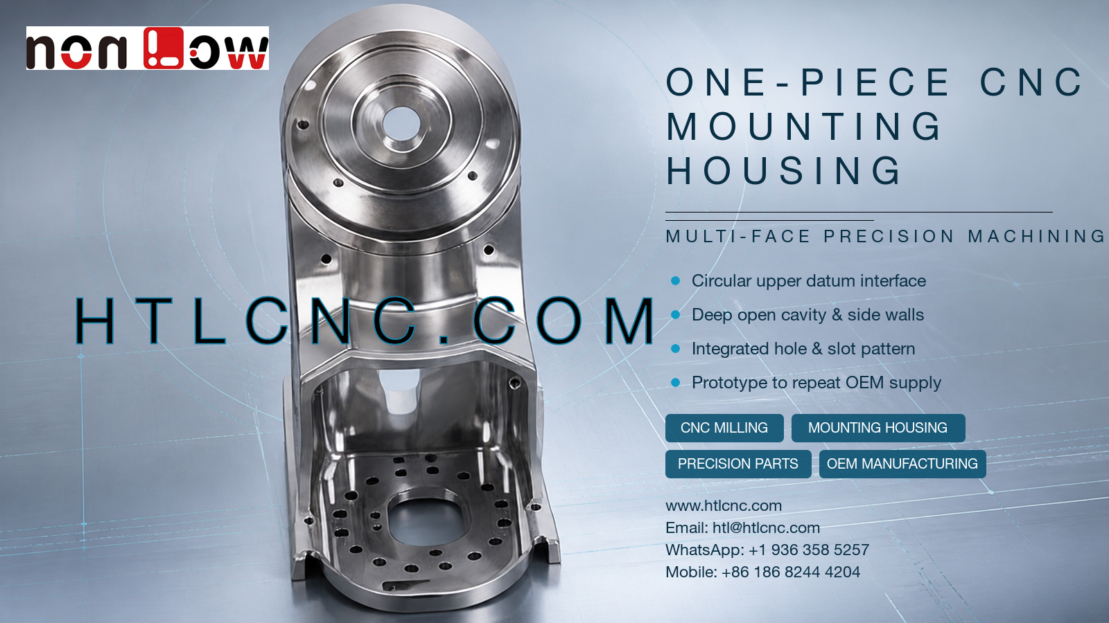
One-piece CNC mounting housing production coordinates a circular upper interface, deep open cavity, integrated side walls and a dense internal hole-and-slot pattern in one precision OEM component.
A one-piece CNC mounting housing can replace several joined brackets when a design requires one continuous structural body with multiple functional zones. The pictured part visibly combines a large circular upper interface, concentric recessed faces, a narrow transition, an open deep cavity, integrated side walls, an internal floor opening and a dense pattern of smaller holes and slots. HTL CNC provides custom CNC machining, precision CNC parts, multi-face CNC milling, prototype validation, low-volume production and repeat OEM manufacturing for overseas equipment builders and product-development teams. The photograph does not confirm material grade, tolerance, load direction or final application; those requirements must follow the customer's released drawing, STEP model and assembly information.
Why Choose a One-Piece Mounting Housing?
Integrating several interfaces into one machined body can reduce separate fasteners, welded joints and stack-up between individual components. That is an engineering interpretation of the visible architecture, not a claim about this pictured part's actual use. The benefit only exists when the design, material, machining route and inspection plan support the required assembly function.
For sourcing teams, an integrated housing also concentrates more risk in one component. A bore, face or hole pattern that is acceptable on its own may still fail assembly if its relationship to another zone is incorrect. Supplier qualification should therefore focus on datum strategy and cross-feature evidence rather than only on a list of individual dimensions.
Circular Upper Interface and Concentric Features
The upper end contains several concentric circular levels around a central opening. A released drawing should identify which diameter locates a mating component, which face provides seating, whether the small surrounding holes form a functional pattern and which axis defines the remainder of the part. Possible controls include diameter, shoulder depth, face flatness, runout, axis position and perpendicularity, but the required controls must be stated by the customer.
Process selection can involve circular interpolation, boring, reaming, face milling or another route chosen from size, access and tolerance. If the circular interface is critical to the lower cavity, the setup plan should preserve that relationship through controlled locating features or coordinated multi-axis access.
Deep Open Cavity and Integrated Side Walls
The lower zone contains an open cavity surrounded by tall walls and changing internal levels. Roughing must remove material while retaining enough stiffness for finishing. Tool diameter, projection, chip evacuation, local wall thickness and clamping support all affect the achievable process. Long-reach tools may be necessary in deep areas, but they also increase deflection and vibration risk.
A stable plan can rough the cavity in stages, leave finishing stock on controlled surfaces and complete the most important floors, walls and openings after stress and heat have been managed. Internal corner radii should reflect functional need and realistic cutter access. Unnecessarily small radii can increase cycle time and tool risk without improving assembly.
Internal Hole and Slot Pattern as an Assembly Datum Chain
The cavity floor visibly contains a central opening, repeated smaller holes and narrow slots. The drawing should distinguish locating holes, tapped holes, clearance holes, fluid or cable openings and non-functional relief features. Position and orientation may matter more than the nominal hole diameter when multiple features locate one internal mechanism.
Hidden intersections and narrow slots also need a deburring and cleaning plan. Loose edges inside an enclosed assembly can interfere with components or become contamination. Inspection may include pin gauges, thread gauges, optical measurement or CMM probing according to accessibility and released requirements.
Multi-Face CNC Machining and Workholding Strategy
The upper circular face, lower cavity, side walls and side-facing holes approach the component from different directions. Some versions may be produced with 3-axis CNC machining and qualified refixturing. Indexed 4-axis or 5-axis CNC machining can be considered when setup reduction improves access or protects relationships among the upper datum, cavity and side interfaces.
Axis count is not a quality guarantee. The selected route must balance rigidity, datum transfer, tool reach, fixture access, batch size, inspection effort and cost. A credible quotation should identify the planned locating surfaces and the features that will be completed in each setup.
Inspection Evidence for OEM Supplier Approval
A risk-based inspection plan may address the upper concentric diameters, circular-face flatness, central opening, cavity depth, wall position, internal floor profile, hole-and-slot pattern, side-hole location and drawing-defined geometric controls. Measurement methods can include micrometers, bore gauges, depth tools, height measurement, gauges, optical systems and CMM inspection according to tolerance and access.
Overseas OEMs may require a first-article inspection report, selected dimensional data or production-lot records. The exact report format, sampling frequency, traceability and retention period should be agreed before quotation. Drawing confidentiality and controlled access to STEP files can also be addressed during supplier onboarding.
Prototype Assembly Review Before Repeat Production
Prototype evaluation should use the real mating parts where possible. Engineering teams can check circular-interface seating, cavity clearance, hole alignment, fastener access, side-wall interference, cable or component routing and surface-finish allowance. Any design correction should be issued through an updated drawing and STEP revision before low-volume ramp-up.
After sample approval, qualified programs, repeatable fixtures, tool-life control, first-piece checks and revision management support repeat-order consistency. Annual demand, order cadence and delivery destination help plan raw material, machine capacity, outside finishing, inspection workload and export packaging. HTL's prototype and low-volume CNC machining service supports this staged path from engineering samples to repeat OEM supply.
Finish Definition and Protective Packaging
The polished appearance in the image does not establish a material or final finish. Customers may specify an as-machined condition, anodizing, plating, passivation, blasting, polishing, painting or another compatible treatment. Drawings should identify masked datums, protected bores, coating allowance, threaded regions and cosmetic zones.
The circular interface, tall side walls and exposed cavity edges need protection during handling and export. Separators, caps, individual wrapping or formed trays can reduce impact and metal-to-metal contact. Packaging labels should connect part number, revision, quantity and lot to the inspection documentation.
RFQ Information for Engineering Review
Send the released 2D drawing and STEP file with material requirements, prototype and production quantities, annual demand, critical datums, upper-interface dimensions, cavity and hole tolerances, threads, finish requirements, inspection-document scope, packaging expectations, requested delivery date and destination. Include mating-part or assembly data when the circular interface, cavity or internal pattern depends on related components. HTL CNC can then review the actual one-piece CNC mounting housing and prepare a manufacturing, inspection and delivery plan based on controlled requirements.
Website: www.htlcnc.com Email: htl@htlcnc.com WhatsApp: +1 936 358 5257 Mobile: +86 186 8244 4204
Have a part ready for engineering review?
Send your drawing, STEP file, material and quantity directly to HTL CNC for a manufacturing quotation.