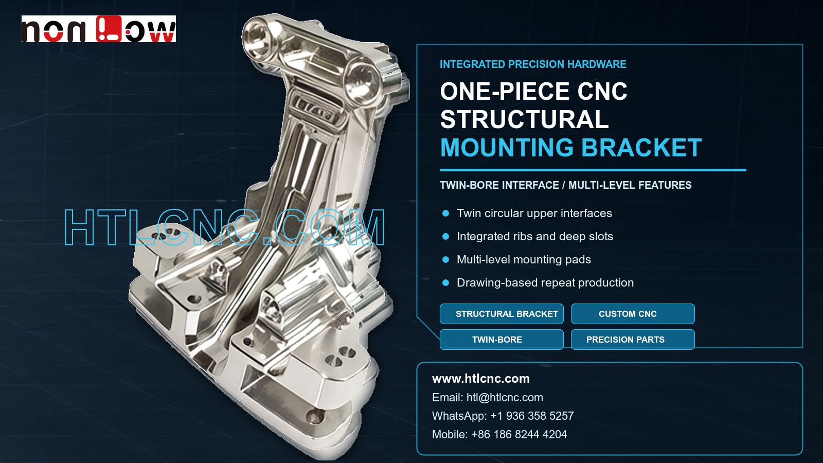
A one-piece CNC structural mounting bracket integrates a twin-bore upper interface, reinforcing ribs, deep slots and multi-level mounting pads in one drawing-based OEM part.
A one-piece CNC structural mounting bracket consolidates alignment, support and fastening features that might otherwise require several separate plates, spacers or joints. The pictured part visibly combines two circular upper interfaces, a tall ribbed body, deep longitudinal slots, multiple side features and broad base mounting pads. This geometry creates a direct relationship between the twin-bore mounting interface and the lower installation points. HTL CNC provides custom CNC machining and drawing-based OEM manufacturing for equipment builders, product-development companies and procurement teams that need precision CNC brackets from prototype validation through low-volume production and repeat orders. The exact material, load case, tolerance and application must be confirmed from released engineering files rather than inferred from the image.
What Is a One-Piece Structural Mounting Bracket?
A one-piece structural bracket is a machined component in which several locating and supporting functions are produced from one body. The visible upper bores may locate shafts, pins, sleeves, bearings or another mating assembly, but their final purpose is not confirmed by appearance. The lower pads provide multiple installation points, while the central ribs and slots appear to connect the upper and lower regions through a continuous machined structure.
For a buyer, the practical value of a one-piece design is not simply a lower part count. It can also reduce stacked-interface variation and eliminate some welded or bolted joints. Whether that benefit applies to a specific project depends on the released design, load path, material and validation plan. The RFQ should identify which interfaces locate the assembly, which surfaces carry load and which dimensions are only clearance or cosmetic features.
Twin-Bore Interface and Positional Control
The two circular upper openings are the most recognizable functional group. Engineering review should define bore diameter, depth, internal steps, center distance, axis relationship and position relative to the base datums. If a bore receives a bearing, bushing, pin, seal or another controlled component, the mating requirement and surface condition should be stated explicitly.
The two openings should be evaluated as a related interface rather than as independent holes. Depending on the drawing, inspection may need to address center distance, common height, parallelism, concentric steps or another geometric relationship. The process route may use circular interpolation, boring, drilling, reaming or other operations selected from the actual geometry and tolerance. No specific fit or tolerance can be claimed from the photograph.
Ribs, Deep Slots and Remaining Stiffness
The central body contains long ribs and recessed channels. These features remove weight and create access while leaving a defined structural path between the upper interface and the mounting base. From a machining perspective, they also change the stiffness of the part as stock is removed. A staged roughing and finishing plan may retain support until the main profile is stable, then complete the deep slots and exposed ribs under controlled clamping.
Tool reach, cutter diameter, chip evacuation and internal corner radii should be reviewed before quotation. If the drawing specifies a narrow slot or nearly sharp internal transition, the customer and supplier should confirm whether standard cutter access is realistic. Deburring must remove loose edges without rounding datum shoulders, changing slot width or damaging the entry to a nearby bore or thread.
Multi-Level Mounting Pads and Datum Strategy
The base includes several pads at different positions and heights, with repeated holes and local pockets. A reliable datum strategy normally begins with the surface that seats against the customer's equipment, then relates the upper twin-bore interface and side features back to that installation condition. If some pads are clearance-only while others control location, the drawing should distinguish them.
Fixture design must support the part without loading thin ribs or blocking access to the deep channels. A 3-axis CNC machining route with qualified refixturing may be appropriate for some versions. Indexed 4-axis or 5-axis CNC machining can be considered when multiple orientations or cross-face relationships justify fewer setups. Axis count is selected according to tool access, datum transfer, rigidity, volume and cost—not as a generic quality claim.
Inspection for a Precision CNC Bracket
Inspection should follow the bracket's assembly function. Relevant characteristics may include base flatness, pad height, bore size, twin-bore center distance, bore-axis relationship, hole-pattern position, slot width and depth, rib profile, side-feature location and drawing-defined geometric controls. Suitable equipment may include calipers, micrometers, depth gauges, bore gauges, pin and thread gauges, height measurement, optical systems and CMM inspection according to access and tolerance.
During supplier qualification, overseas OEMs can request a first-article inspection report or selected results tied to critical characteristics. Repeat production may use defined in-process checks and lot-level records. The sampling plan, report format, traceability and document retention period should be agreed before quotation so the included quality evidence is clear.
Surface Finish and Handling Protection
The part may be supplied as machined or with a customer-specified treatment compatible with the released material. Potential options can include anodizing, plating, passivation, blasting, brushing, polishing, painting or another controlled finish, but the correct choice cannot be determined from the image. Coating allowance, masked bores, protected datum faces, plugged threads and cosmetic zones should be documented in the finish specification.
The upper circular interfaces and polished edges are vulnerable to impact during transfer and export shipping. Protective caps, separators, individual wrapping or formed trays can reduce metal-to-metal contact. Packaging labels should identify part number, drawing revision, quantity and lot so receiving inspection and repeat-order traceability remain connected to the controlled source files.
Prototype Validation Before Repeat OEM Supply
A prototype should be evaluated in the real assembly. Buyers can verify seating on the mounting pads, twin-bore alignment, mating-part fit, fastener access, side-feature clearance, structural behavior under the intended test condition, finish compatibility and packaging protection. Any design or tolerance change should be released under a new revision before ramp-up.
After approval, controlled programs, qualified workholding, defined inspection points and formal change management support repeat-order consistency. Batch size, annual demand, delivery schedule and destination help HTL CNC evaluate fixture investment, machine capacity, finishing lots, inspection workload and export planning. Drawing confidentiality and access to controlled files can be included in the supplier-onboarding discussion.
RFQ Information for Engineering Review
Send the released 2D drawing and STEP file with the specified material, prototype and production quantities, annual demand, critical bores and datum relationships, threads, surface finish, inspection-document needs, packaging expectations, delivery schedule and destination. Include a mating sample or assembly model when the upper interfaces depend on related components. HTL CNC can then review the actual one-piece CNC structural mounting bracket and prepare a process and quality plan based on controlled requirements rather than assumptions.
Website: www.htlcnc.com Email: htl@htlcnc.com WhatsApp: +1 936 358 5257 Mobile: +86 186 8244 4204
Have a part ready for engineering review?
Send your drawing, STEP file, material and quantity directly to HTL CNC for a manufacturing quotation.